
Attention.
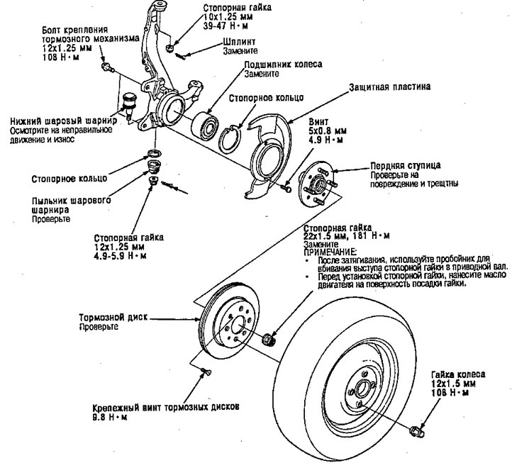
- Replace self-locking nuts after removal.
- The vehicle should be lowered to the ground before tightening the bolts and nuts associated with the rubber mounts and bushings.
- Screw the lock nut to the lowest torque rating, then tighten until the slot in the nut is aligned with the hole for the cotter pin. Do not combine the nut by loosening.
Note:
- Use only genuine Honda weights for aluminum wheels. Non-original weights may corrode or damage aluminum wheels.
- On aluminum wheels, remove the center cap from the inside of the wheel after removing the wheel.
- Before installing the brake discs, clean the mating surfaces of the front hub and brake discs.
- Before installing the wheel, clean the mating surfaces of the brake disc and wheel and remove any grease before tightening the ball joint nut.
1. Slightly loosen the wheel nuts.
2. Raise the front of the machine off the ground and secure it to safety stands in appropriate locations.
3. Remove the wheel nuts and wheels.
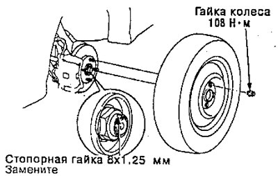
4. Lift up the locking tab on the lock nut, then remove the nut.
Note:
- Once tightened, use a punch to drive the lock nut flange into the drive shaft.
- Before installing the lock nut, apply engine oil to the nut seating surface.
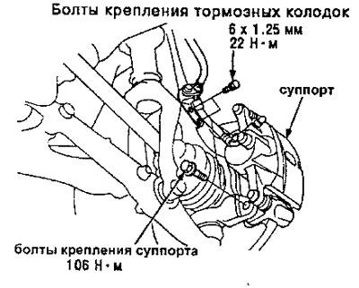
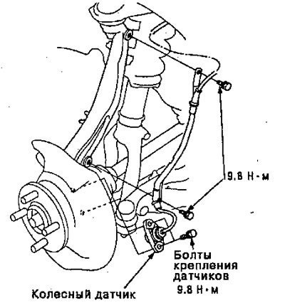
5. Remove the brake hose mounting bolts.
6. Remove the brake pad mounting bolts and hang the caliper on one side.
Caution: To prevent accidental damage to the caliper or brake hoses, hang the brake mechanism from the chassis using a short piece of wire.
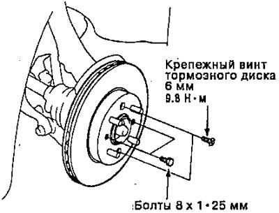
7. Remove the M6 screws securing the brake discs.
8. Screw the M8 x 1.25 bolts into the disc to push it away from the hub.
Note: Turn each bolt two turns at a time to prevent excessive kinking of the disc.
9. Remove the brake disc from the steering knuckle.
10. Remove the wheel sensor from the steering knuckle.
Note: Do not disconnect the sensor connector.
Note: Use a special tool to separate the ball joints from the suspension or steering arm.
Caution: Be careful not to damage the ball joint boot.
11. Remove any dirt or grease from the ball joint.
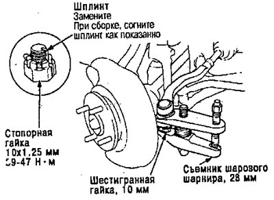
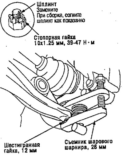
12. Remove the cotter pin from the steering arm and remove the nut.
13. Screw the M10 hex nut onto the ball joint pin. Make sure the nut is seated flush with the end of the ball joint pin to prevent the puller from damaging the threaded part of the ball joint.
14. Apply lubricant to the special tool in the indicated places. This will make it easier to install the tool and prevent damage to the threads of the tightening bolt
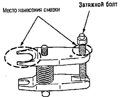
15. Install the special tool as indicated. Insert the jaws carefully, being careful not to damage the ball joint boot. Adjust the clamp gap by turning the tightening bolt.
Note: If necessary, apply penetrating lubricant to loosen the ball joint.
16. With the tool in place, turn the adjusting bolt to align the arms parallel. Then tighten the pinch bolt by hand and check the jaws again to make sure they are still parallel.
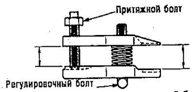
7. Using a wrench, tighten the tie bolt until the ball joint pin pops out of the steering arm.
Warning. The ball joint may suddenly pop out or break and spray dirt or debris into your eyes.
18. Remove the tool, then remove the nut from the end of the ball joint and slide the ball joint out of the steering/suspension arm. Inspect the ball joint boot and replace it if damaged.
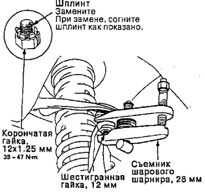
19. Remove the lower arm ball joint cotter pin and nut.
20. Screw the M12 hex nut onto the ball joint pin. Make sure the nut is flush with the end of the ball joint pin, otherwise the threaded portion of the ball joint may be damaged by the ball joint puller.
21. Use a special tool to separate the ball joint and lower control arm. APPLICATION: If necessary, apply penetrating lubricant to loosen the ball joint.
22. Remove the cotter pin and upper ball joint nut.
23. Screw the M12 hex nut onto the ball joint. Make sure the nut is seated flush with the end of the ball joint pin to prevent the ball joint puller from damaging the threaded part of the ball joint.
24. Use a special tool to separate the ball joint from the steering knuckle.
Note: If necessary, apply penetrating lubricant to loosen the ball joint.
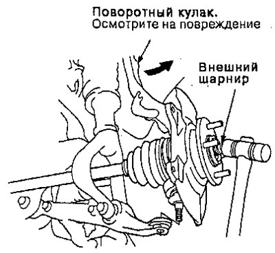
25. Push the steering knuckle outward and remove the driveshaft outer joint from the cam by tapping the end of the drive shaft with a plastic hammer, then remove the steering knuckle.
Replacing the wheel bearing.
Note: Replace the bearing with a new one after removal.
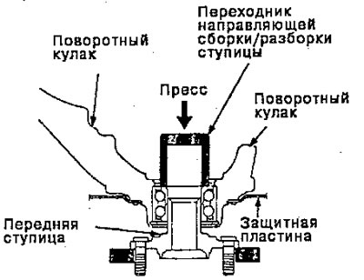
26. Separate the hub from the steering knuckle using a special tool and a hydraulic press.
Attention.
- Be careful not to deform the protection plate.
- Hold the hub so that it does not fall while pressing out.
- To prevent damage to the tool, make sure the threads are fully tightened before pressing out.
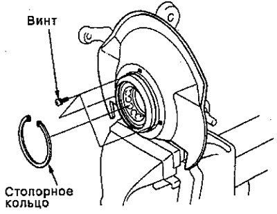
27. Remove the retaining ring and skid plate from the steering knuckle.
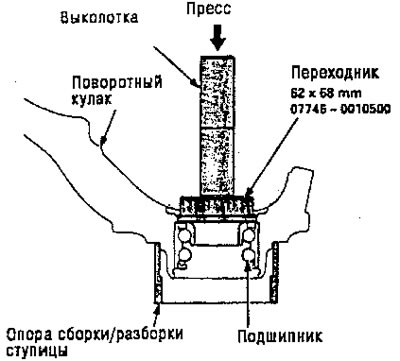
28. Press the wheel bearing out of the steering knuckle using a special tool and a press.
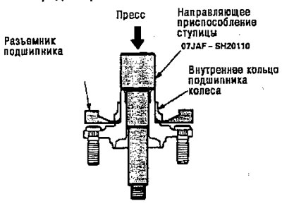
29. Remove the inner bearing race from the hub using the special tool shown and a commercially available bearing remover.
Attention. To prevent damage to the tool, ensure that the threaded parts are fully tightened before pressing out.
Note: Wash the steering knuckle and hub thoroughly in solvent before assembly.
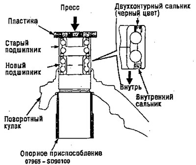
30. Press the new wheel bearing into the steering knuckle using the old bearing, plate and press.
Note: Place the wheel bearing on the steering knuckle with the inner seal (metallic color) inside the fist. Be careful not to damage the inner seal.
31. Securely install the snap ring into the groove of the steering knuckle.
32. Install the skid plate and tighten the screws.
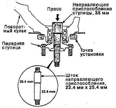
33. Install the hub onto the steering knuckle, using the special tools as indication.
Attention. Be careful not to damage the protection plate.
34. Install parts in the reverse order of removal.