
Note: Resistance varies with coil temperature: nominal values are given at 20°C.
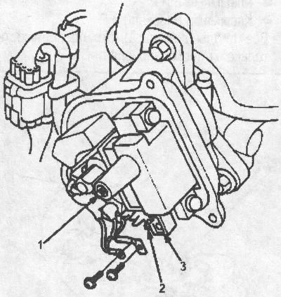
Primary resistance (between terminals A and B): 0.63-0.77 ohm
Secondary winding resistance (between terminals A and B of the secondary winding): 12.8-19.2 ohm
1. terminal of the secondary winding; 2. terminal a (+); 3. terminal in (-)
Testing the signal at the input of the ignition control module (ICM)
1. Remove the cover, slider and rear cover of the distributor.
2. Disconnect the wires from the ICM.
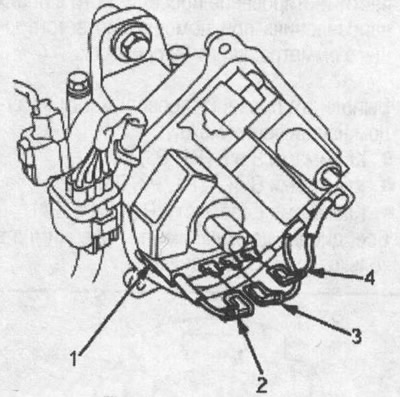
1. ICM block; 2. yellow-green wire; 3. black and yellow wire; 4. white-blue wire
3. Turn the ignition switch to the ON position (II). Check for voltage between the BLACK/YELLOW wire and chassis ground. There should be battery voltage.
- If there is no battery voltage, check the BLACK/YELLOW wire between the under-dash fuse/relay box and the ICM.
- If there is battery voltage, go to step 4.
4. Turn the ignition key to the ON position (II). Check for voltage between the WHITE/BLUE wire and chassis ground. There should be battery voltage.
- If there is no battery voltage, check:
- ignition coil
- WHITE/BLUE wire between ignition coil and ICM
- If there is battery voltage, go to step 5.
5. Check for continuity through the BLUE wire between the tachometer connector and the ICM. Conductivity should be
6. Check for continuity through the BLUE wire to chassis ground. There should be no conduction.
7. If all checks are normal, replace the ICM.