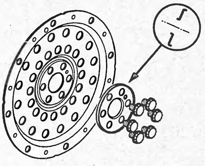
Removal and installation
Note:
- Installation is carried out in the reverse order of removal.
- Tightening torques are given in the text.
- After installation, calibrate the starter clutch.
1. Raise the vehicle.
2. Remove the protective covers.
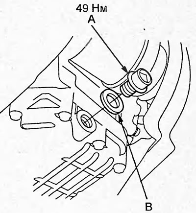
3. Unscrew the drain plug "A" and drain the CVT working fluid. Install the plug with a new gasket "B".
4. Disconnect the negative battery terminal and then the positive one.
5. Remove the bracket, tray and battery.
6. Remove the air filter and air duct.
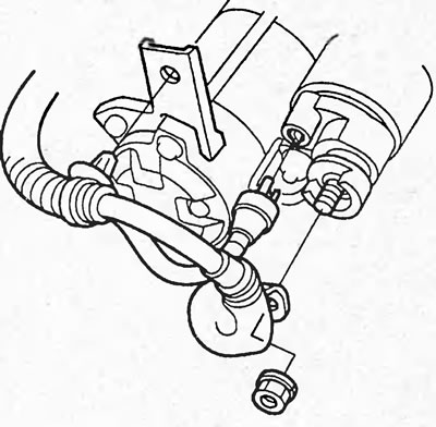
7. Disconnect the wires from the starter and remove the wire from the bracket.
Tightening torque - 9 Nm
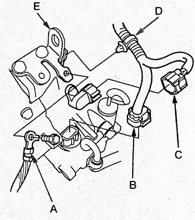
8. Loosen the bolt and disconnect the ground wire (A). Disconnect the solenoid valve block connector (B) and the drive pulley speed sensor connector (C). Disconnect the wire retainer (D) from the bracket (E).
9. Remove the cotter pin (A) and washers (B) and disconnect the variator control cable (C) from the lever (D).
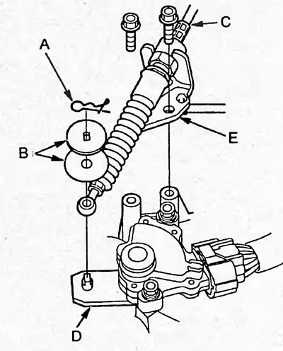
10. Loosen the bolts and remove the bracket (E) with the cable.
Tightening torque: 22 Nm
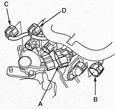
11. Disconnect the connectors of the selector position sensor (A), the driven pulley speed sensor (B), and speed sensors No.1 (C) and No.2 (D).
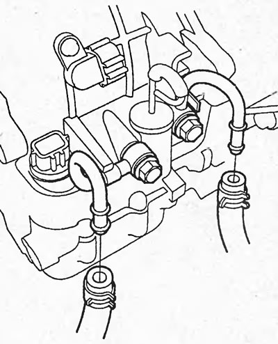
12. Disconnect the CVT fluid hoses.
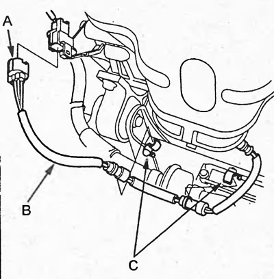
13. Disconnect the oxygen sensor connector (A) and remove the wire (B) from the clips (C).
14. Unscrew the nut and remove the front support bolt.
Tightening torque - 64 Nm
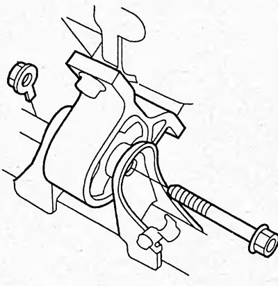
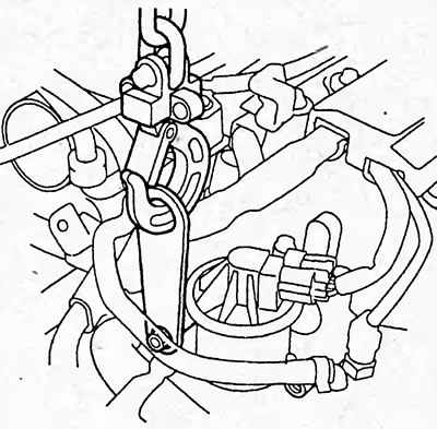
15. Install the engine suspension bracket.
16. Using a hex key (A) (5 mm) to hold the pin (C) of the ball joint (B) of the stabilizer link, loosen the nut. Disconnect the front suspension stabilizer link from the front suspension lower arm (D).
Tightening torque - 39 Nm
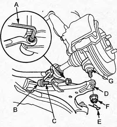
17. Remove the cotter pin (E) and unscrew the nut (F). Disconnect the lower arm (D) of the front suspension from the steering knuckle (G).
Tightening torque - 49 Nm
18. Remove the front drive shafts (see chapter "Drive shafts").
19. Remove the exhaust pipe (A) with the catalytic converter and the gasket (B).
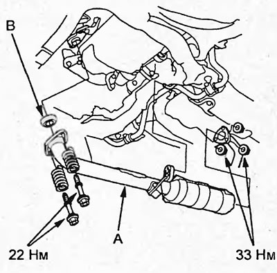
20. Loosen the bolts and remove the stiffeners (A) and cover (B).
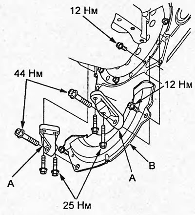
21. Rotate the crankshaft and unscrew the 8 bolts.
Tightening torque - 12 Nm
22. Unscrew the rear support bolts.
Tightening torque - 59 Nm
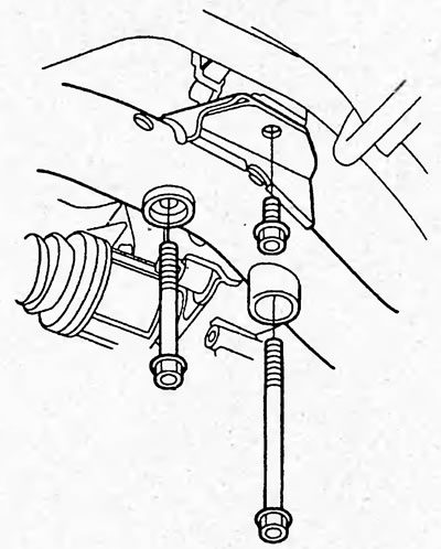
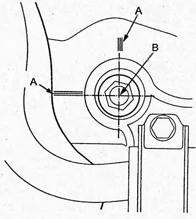
23. Apply marks (A) as shown in the figure on the center of the bolt (B) (10 mm).
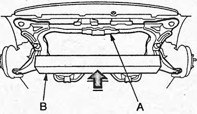
24. Place a wooden block (B) under the subframe (A) as shown in the figure.
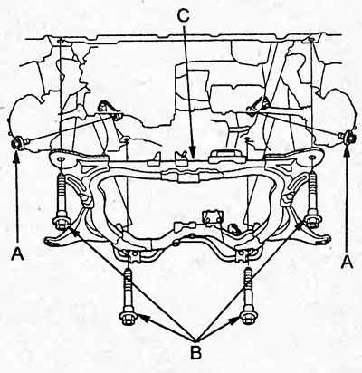
25. Remove the bolts (A), then remove the mounting bolts (B) and remove the subframe (C).
Tightening torque:
- bolt "A" - 59 Nm
- bolt "B" - 103 Nm
26. Remove the drive shaft (A) from the variator.
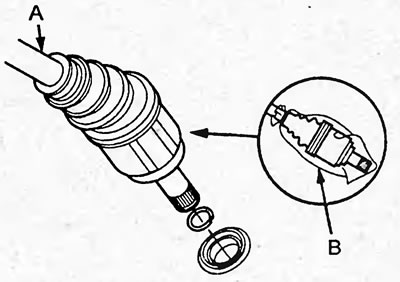
27. Wrap the drive shaft with a rag (B) as shown in the figure.
28. Jack up the variator.
29. Unscrew the variator mounting bolts shown in the figure.
Tightening torque - 64 Nm
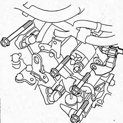
30. Loosen the bolts and nuts and remove the variator support bracket.
Tightening torque - 54 Nm
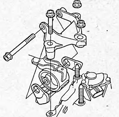
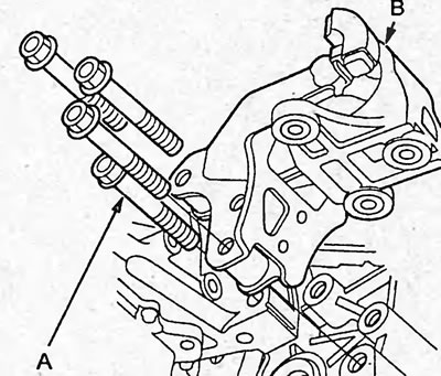
31. Loosen the bolts (A) and remove the bracket (B) of the rear variator support.
Tightening torque - 64 Nm
32. Make sure all wires and tubes are disconnected from the variator.
33. Move the variator away from the engine and lower the variator.
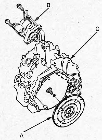
34. Remove the flywheel (A) and starter (B) from the variator (C).
Note: When installing the flywheel, apply high temperature grease to the engine output shaft splines.
Tightening torque - 44 Nm
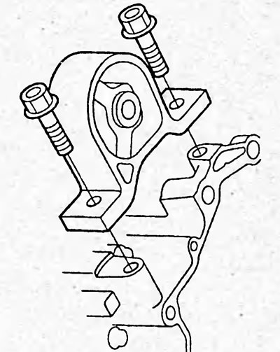
35. Loosen the bolts and remove the front support.
Tightening torque - 64 Nm
36. If necessary, remove the flywheel drive plate.