
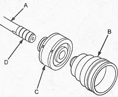
2. Install the dynamic damper (C) and boot (B) onto the drive shaft (A).
3. Remove the protective tape.
4. Align the marks (A) on the drive shaft (C) and the inner race (B) of the inner joint and install the race.
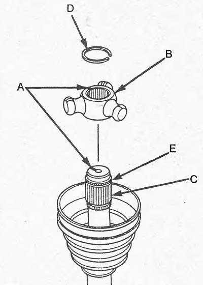
5. Install the snap ring (D) into the groove (E) of the drive shaft.
6. Install the rollers (A) on the inner race (C) in accordance with the marks (B).
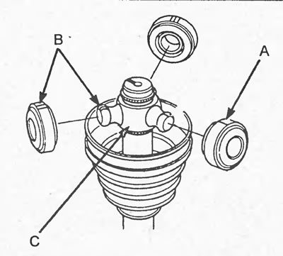
7. Fill the outer race of the inner joint with grease.
Grease - U131-15 MAX BS No.1
Amount of grease:
- Models with D17A engine and 4WD models - 130 - 140 g
- The rest - 100-110 g
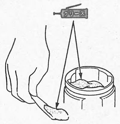
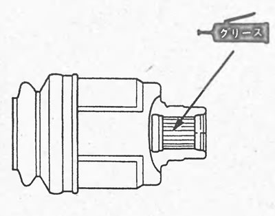
8. (4WD models (left side)) Apply grease to the splines of the outer race of the joint.
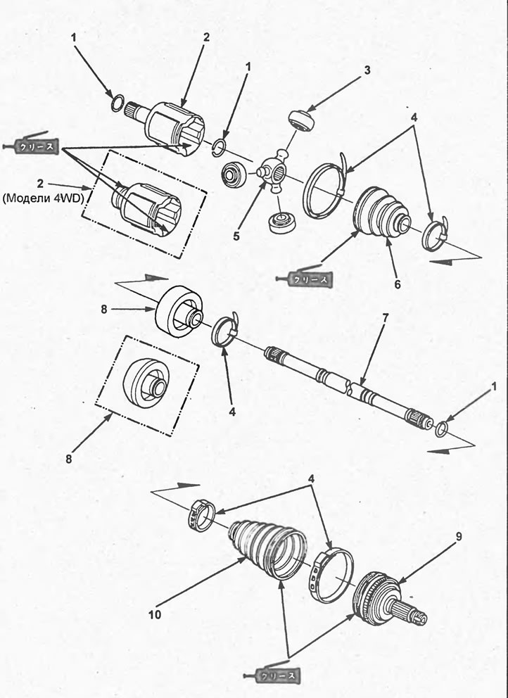
Disassembly and assembly of the drive shaft. 1 - retaining ring, 2 - outer race of the inner joint, 3 - roller, 4 - clamp, 5 - inner race of the inner joint, 6 - inner joint boot, 7 - drive shaft, 8 - dynamic damper, 9 - outer joint, 10 - outer joint boot.
Lubrication - CS No.1
Amount of lubricant - 0.5-1.0 g
9. Install the outer race (B) of the inner joint, aligning the marks (C) on the rollers (A) and the outer race.
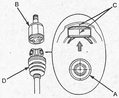
10. Place the cover (D) onto the outer race.
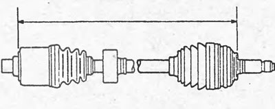
11. Install the drive shafts so that their length complies with the standard.
Length of drive shafts:
- Right Drive Shaft: D17A Engine Models and 4WD Models - 502 - 507 mm
- 2WD models
- with D15B engine - 498 - 503 mm
Left drive shaft:
4WD models - 506 - 511 mm
d17A engine:
- Manual transmission - 788 - 793 mm
- Automatic transmission, variator (CVT) 792 - 797 mm
d15B engine:
- Manual transmission - 784 - 789 mm
- Automatic transmission, variator (CVT) - 787 - 792 mm
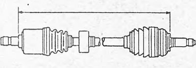
Right and left (2WD models) drive shafts.
Left drive shaft (4WD models).
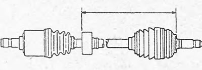
12. Adjust the position of the dynamic damper so that the distance shown in the figure complies with the standard.
Nominal distance:
Right drive shaft:
- 2WD models with D17A engine - 261.5 - 265.5 mm
- 4WD models - 258 - 262 mm
Left drive shaft:
- 2WD models 478 - 482 mm
- 4WD models - 268 - 272 mm
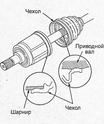
13. Install the inner hinge boot as shown in the figure.
14. Pass the clamp (A) through the fastener (B) 2 times to make 2 loops.
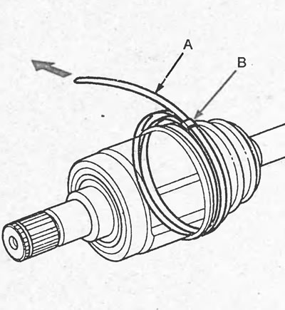
15. Tighten the clamp (A) and place a mark on the clamp so that the distance between the mark (C) and the retainer is 10-14 mm.
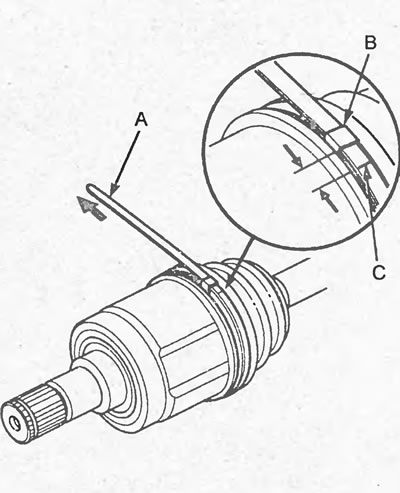
16. Install the special tool (A) and, by turning the adjusting bolt (B), tighten the clamp so that the retainer is set according to the mark (C).
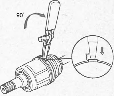
17. Turn the special tool 90° as shown in the figure and screw the locking pin into the center.
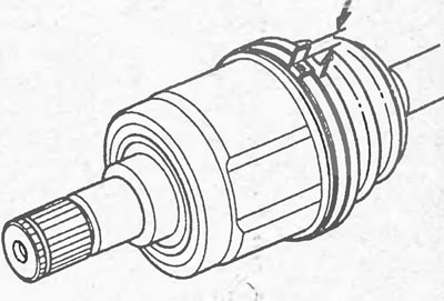
18. Cut the clamp so that the distance shown in the figure is 5-10 mm.
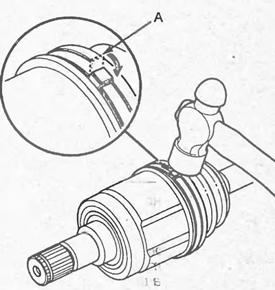
19. Bend the clamp (A) as shown in the figure.
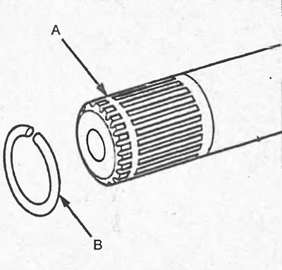
20. Install the snap ring (B) into the groove (A) of the drive shaft.
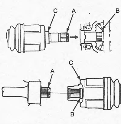
21. Wind the protective tape (C) onto the splines of the drive shaft (A) on the outer joint side.
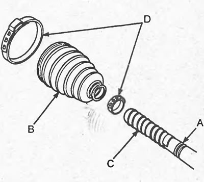
22. Install the clamps (D) and boot (B) onto the drive shaft.
23. Remove the protective tape.
24. Press the retaining ring in the places shown in the figure and install the drive shaft into the joint.

25. Finally install the drive shaft into the joint as shown in the figure.
Note: When performing this procedure, ensure that the drive shaft and the hinge shaft are aligned.
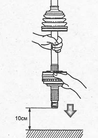
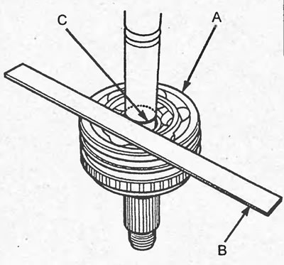
26. Using a ruler (B), make sure that the mark (C) is level with the end of the hinge (A).
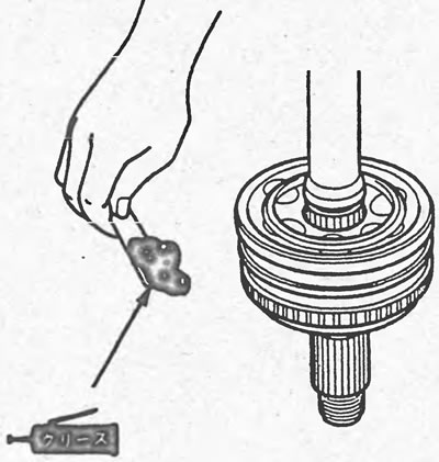
27. Apply grease to the hinge.
Grease - U1651-62
Amount of grease:
- Models with D17A engine and 4WD models - 135 -145 g
- 2WD models (except for models with D17A engines) — 95-105 g
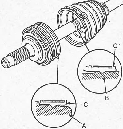
28. Install the boot (C) so that it fits into the grooves of the drive shaft (B) and the joint (A), as shown in the figure.
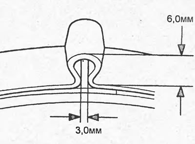
29. Using the special tool, tighten the clamp so that the loop dimensions correspond to those shown in the figure.

30. Make sure the clamps are not loose. Remove any grease that comes out.