Contents: Checking the starting system circuit ⇊ Removal and installation ⇊ Disassembly and assembly ⇊ Examination ⇊
Checking the starting system circuit
Note:
- Operations should be performed at a temperature of 15-38°.
- After performing the operations, it is necessary to erase the fault codes.
- It is recommended to use a starting system tester.
1. Connect the following devices as shown in the figure:
- ammeter (0 - 400 A);
- voltmeter (0 - 20 V);
- tachometer.
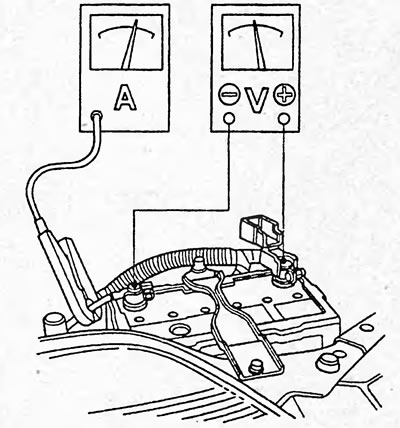
D15B, D17A.
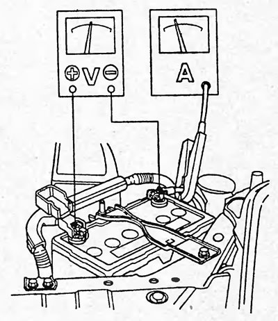
K20A.
2. Remove fuse No.17 (15A) (K20A), No.46 (15A) (D15B, D17A) mounting block of relays and fuses.
3. Press the clutch pedal or set the automatic transmission selector to position "P" and turn the ignition key to the "START" position (|||).
Does the starter rotate the crankshaft normally?
- "Yes" - the starting system is OK.
- "No" - if the starter does not rotate the crankshaft, then go to point "4". If the rotation speed is too low or unstable, then go to point "7".
Check the starter if necessary.
4. Check the battery. Check the wiring between the battery and the starter.
Does the starter rotate the crankshaft normally?
- "Yes" - the starting system is OK.
- "No" - go to point "5".
5. Make sure that the automatic transmission selector is in the "P" position and the gear shift lever is in neutral.
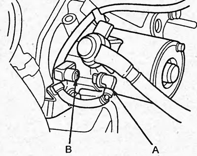
(K20A) Disconnect the starter wire connector (A) and the wire harness connector (B).
(D15B, D17A) Disconnect the BLK/WHT wire (A) from the starter solenoid (B).
Install a jumper wire between the positive battery terminal and connector terminal (A).
D15B, D17A (sedan models with automatic transmission).
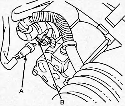
D15B, D17A (others).
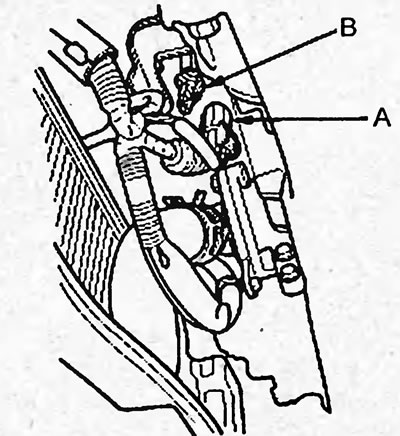
K20A.
Does the starter rotate the crankshaft normally?
- "Yes" - go to point "6".
- "No" - check the BLK/WHT wire between the starter wire connector and the starter, if it is OK, check the starter.
6. Check the following.
- Wire from the starter terminal, wiring and connectors between the starter, ignition switch and relay and fuse box.
- Ignition switch.
- Start inhibit switch;
- Starter relay.
7. Check the crankshaft speed when turning the starter.
Rotation speed -100 rpm
Does the rotation speed correspond to the specified one?
- "Yes" - go to point "8".
- "No" - check the starter.
8. Check the voltage and current when turning the starter.
Voltage:
- D17A - not less than 8.0 V
- D15B (4WD models with manual transmission) — not less than 8.5 V
- D15B (sedan models with automatic transmission) — not less than 10.0 V
- D15B, D17A others - not less than 9.0 V
- K20A - not less than 8.7 V
Current strength:
- D17A — no more than 200 A
- D15B (4WD models with manual transmission) — no more than 350 A
- D15B (sedan models with automatic transmission) — no more than 235 A
- D15B, D17A others - no more than 150 A
- K20A - no more than 230 A
- "Yes" - go to point "9".
- "No" - check the starter.
9. Check the starter gears, flywheel or torque converter drive plate for damage or other faults.
Removal and installation
1. Disconnect the wires from the positive and negative terminals of the battery.
2. (D15B, D17A) Remove the intake resonator.
3. (K20A) Disconnect the knock sensor connector.
4. (K20A) Loosen the bolt (A) securing the wiring harness bracket, then remove the intake manifold brackets.
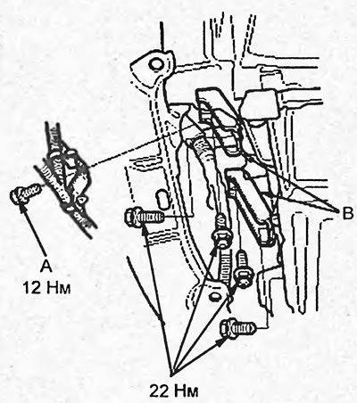
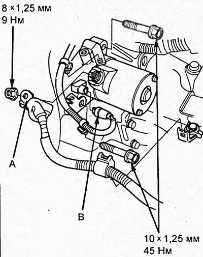
5. Disconnect the starter wire (A) from the "B" terminal, then disconnect the BLK/WHT wire (B) from the "S" terminal.
D15B, D17A (sedan models with automatic transmission).
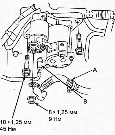
D15B, D17A (others).
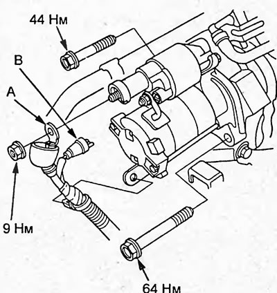
K20A.
6. Unscrew the two starter mounting bolts and remove the starter.
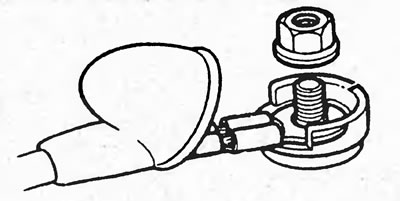
7. Install the parts in the reverse order of removal. Connect the wire to terminal "B" as shown in the figure.
Disassembly and assembly
1. Remove the parts in the order shown in the figures "Disassembling and assembling the starter".
2. Installation of parts is carried out in the reverse order of removal.
Note on assembly of starter Denso (1.0 kW), Mitsuba (1.0 kW):
1. Bend the brush springs slightly with a flat-head screwdriver as shown in the figure, then install the brushes so that they protrude halfway from the brush holder and release the springs so that they lock the brushes in place.
Note: When installing new brushes, do the following. Wrap the armature commutator with #500-600 sandpaper, grains outward, and rotate the armature smoothly. The contact surfaces of the brushes will wear down to the required size, after which the brushes will fit correctly to the commutator.
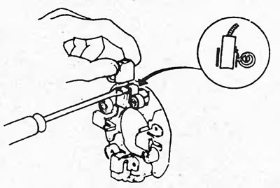
2. Install the anchor into the holder and install the brush holder. Bend the brush springs and press the brushes into the brush holder until they are in the desired position on the commutator and release the brush springs.
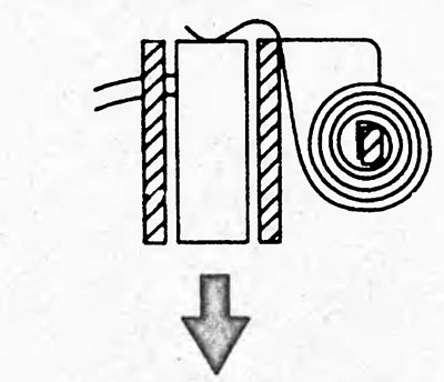
3. Install the starter protective plate to secure the brush holder.
Denso (0.8 kW):
1. Install the armature into the starter housing, install the brush holder and brushes. Note: when installing new brushes, do the following. Wrap the armature commutator with #500-600 sandpaper, grains outward, and rotate the armature smoothly. The contact surfaces of the brushes will wear down to the required size, after which the brushes will fit correctly to the commutator.
2. Compress the brush springs and install them into the brush holder.
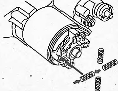
3. Install the brush holder protective plate and the rear cover.
Mitsuba (0.8 kW):
1. Install the brushes into the brush holder and install the armature (B) into the brush holder (A).
Note: When installing new brushes, do the following. Wrap the armature commutator with #500-600 sandpaper, grains outward, and rotate the armature smoothly. The contact surfaces of the brushes will wear down to the required size, after which the brushes will fit correctly to the commutator.
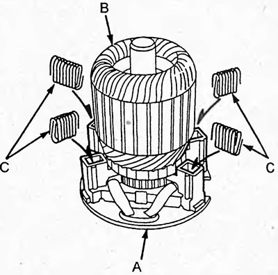
2. Compress the brush springs (C) and insert them into the brush holder as shown in the figure above. Press them from above to get them into position.
3. Install the armature and brush holder assembly into the starter housing.
Examination
Checking the anchor
1. Check the collector for an open circuit. Using an ohmmeter, check for continuity between the collector lamellas.
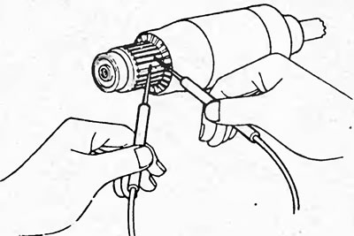
If there is no conductivity, replace the anchor.
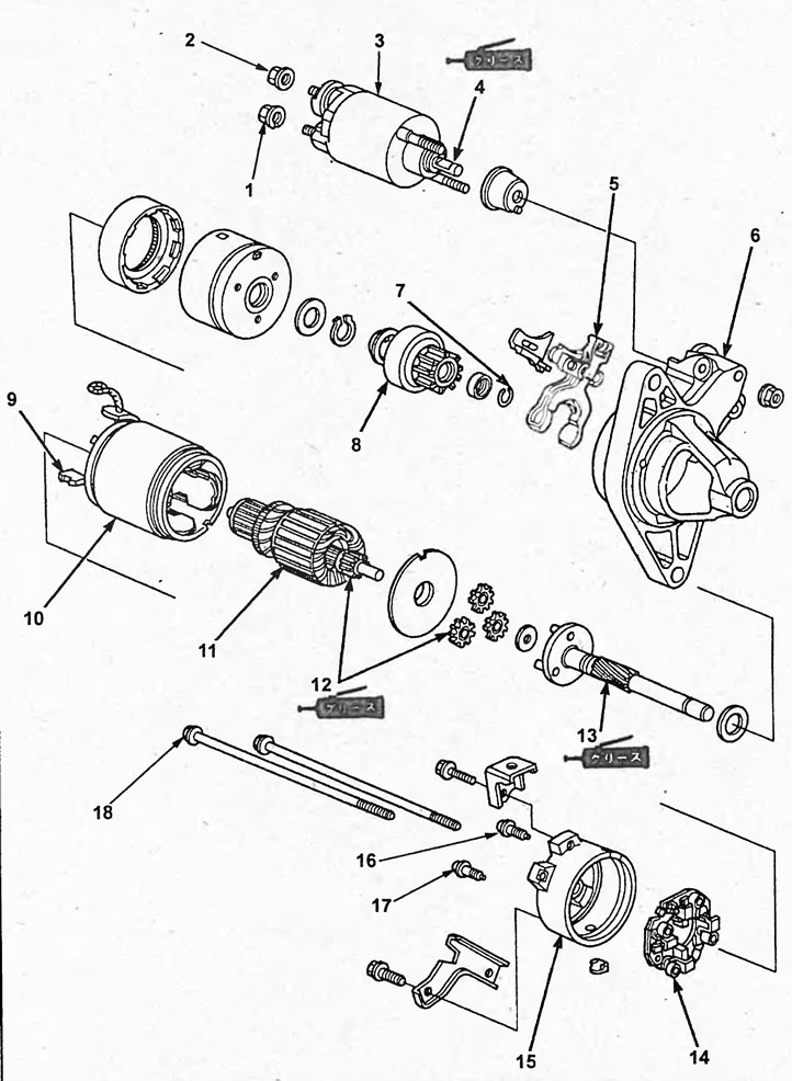
Disassembly and assembly of the starter (D17A, K20A (Denso (1.0 kW))). 1, 2 - nuts, 3 - traction relay assembly, 4, 12, 13 - lubricate (molybdenum disulfide grease), 5 - return lever, 6 - drive mechanism housing, 7 - washer, 8 - overrunning clutch, 9 - brush, 10 - starter housing, 11 - anchor, 14 - brush holder, 15 - rear cover, 16, 17 - screws, 18 - tie bolts.
2. Check for short circuit of the armature winding to ground. Using an ohmmeter, check for conductivity between the collector and the armature winding core.
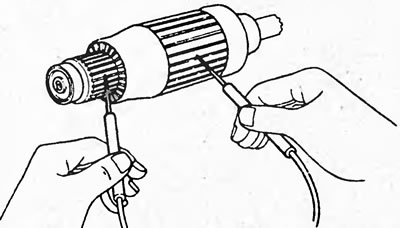
If there is conductivity, replace the anchor.
Checking the collector
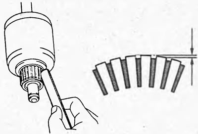
1. Inspect the working surfaces of the collector lamellas; if they are dirty or burnt, clean the working surfaces with #500-600 sandpaper or turn the collector on a lathe.
2. Mount the anchor on the prisms and measure the collector runout.
Nominal runout:
- "Denso" (0.8 kW) - 0.05 mm
- the rest - 0.02 mm
Maximum runout:
- "Denso" (0.8 kW) - 0.4 mm
- the rest - 0.05 mm
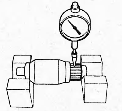
If the runout exceeds the specified value, then turn the commutator on a lathe.
3. Using a caliper, measure the diameter of the manifold.
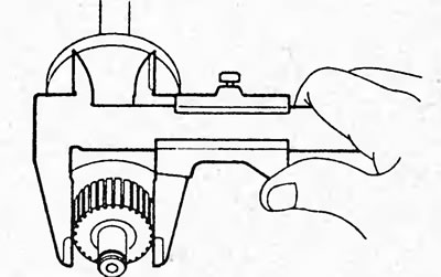
Nominal diameter - 28.0 mm
Minimum diameter:
- Denso - 27.0 mm
- Mitsuba - 27.5 mm
If the collector diameter is less than the minimum value, replace the starter armature.
4. Check that the collector grooves are not contaminated with foreign particles.
Nominal value:
- starters "Denso" - 0.45-0.75 mm
- mitsuba starters - 0.4-0.5 mm
Minimum value:
- starters "Denso" - 0.2 mm
- mitsuba starters - 0.15 mm
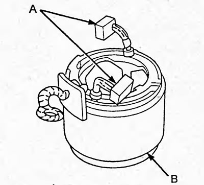
Stator check
Denso - 1.0 kW
1. Check for conductivity between the brushes (A).
2. Check the resistance between each brush and the starter housing (B).
Resistance - not less than 0.01 MOhm
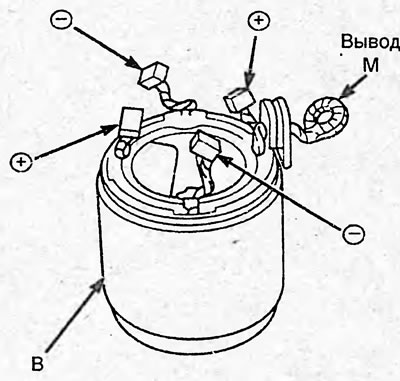
Denso, 0.8 kW
1. Check for conductivity between the positive brushes "+" and the terminal "M".
2. Check for continuity between the negative brushes and the starter housing (B).
3. Check for continuity between the negative brushes and the positive brushes
4. Check the resistance between each positive "+" brush and the starter housing (B).
Resistance - not less than 0.01 MOhm
Checking the brushes
Use a caliper to measure the length of the brushes.
Nominal length:
- "Denso" (1.0 kW) - 14.0-14.5 mm
- "Denso" (0.8 kW) - 9.7-10.3 mm
- "Mitsuba" (1.0 kW) - 15.8-16.2 mm
- "Mitsuba" (0.8 kW) - 11.1-11.5 mm
Minimum length:
- "Denso" - (1.0 kW) 9.0 mm
- "Denso" (0.8 kW) - 6.0 mm
- "Mitsuba" (1.0 kW) - 11.0 mm
- "Mitsuba" (0.8 kW) - 4.3 mm
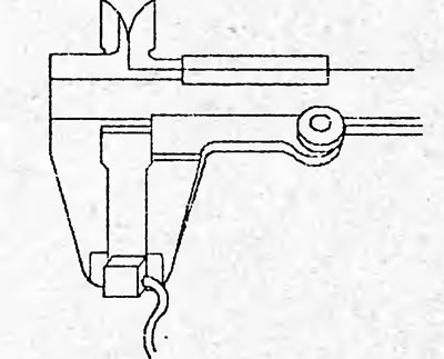
If the brush height is less than the minimum permissible value, replace the brushes and stator winding.
Checking the brush springs
Using a spring balance, measure the tension of the brush springs at the moment they break away from the brush.
Nominal force:
- "Denso" (1.0 kW) - 13.7-17.7 N
- "Mitsuba" (1.0 kW) - 15.7-17.7 N
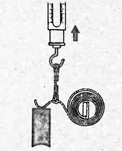
If the spring force is not within the specified range, replace the brush springs.
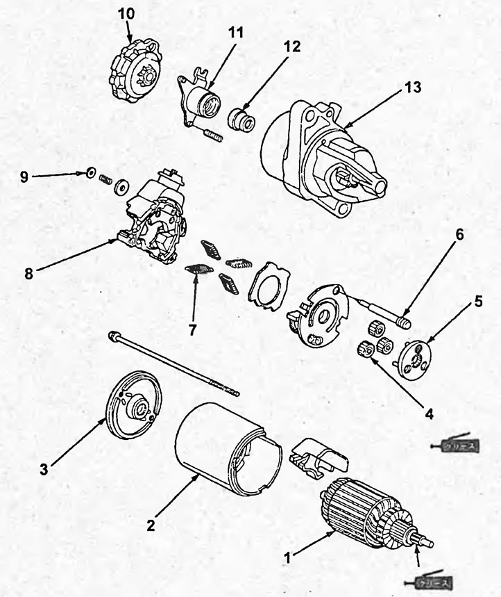
Disassembly and assembly of the starter (D15B, sedan models with automatic transmission (Mitsuba (0.8 kW))). 1 - anchor, 2 - starter housing, 3 - protective plate, 4 - planetary gears, 5 - overrunning clutch, 6 - clutch shaft, 7 - brush springs, 8 - brush holder, 9 - thrust washer, 10 - protective cover, 11 - return plunger housing, 12 - return plunger, 13 - cover.
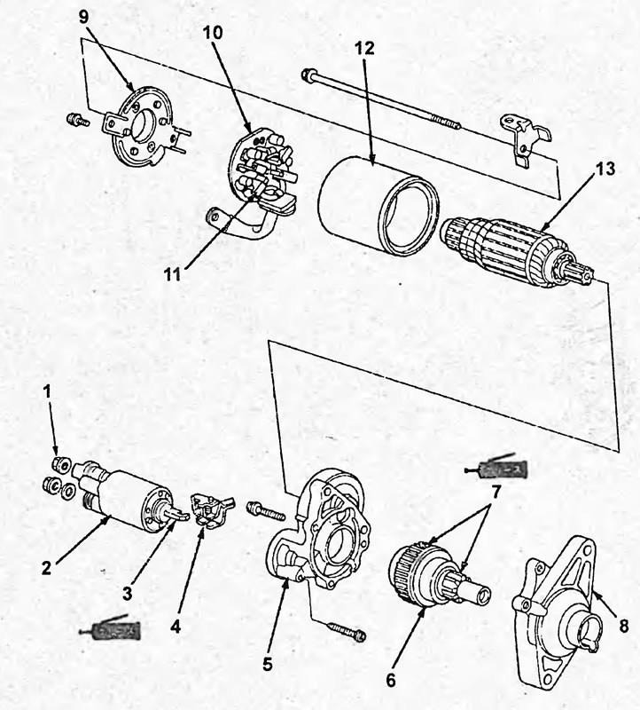
Disassembly and assembly of the starter (D15B, 4WD models with manual transmission (Mitsuba (1.0 kW))). 1 - nut, 2 - traction relay, 3, 7 - apply grease (molybdenum disulfide grease), 4 - electromagnetic return lever, 5 - drive mechanism housing, 6 - overrunning clutch assembly, 8 - drive mechanism cover, 9 - protective plate, 10 - brush holder, 11 - brushes, 12 - starter housing, 13 - anchor.
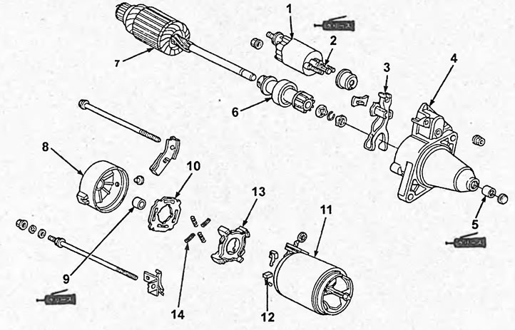
Disassembly and assembly of starter (D15B, D17A others (Denso (0.8 kW))). 1 - traction relay, 2 - lubricate (molybdenum disulfide grease), 3 - return lever, 4 - drive mechanism housing, 5 - front bearing (molybdenum disulfide grease), 6 - overrunning clutch, 7 - anchor, 8 - rear cover, 9 - rear bearing (molybdenum disulfide grease), 10 - protective plate, 11 - starter housing, 12 - brushes, 13 - brush holder, 14 - brush springs.
Checking the brush holder (except Denso (0.8 kW))
Check for continuity between the positive "+" (A) and negative (B) brush holders. If not, replace the brush holder.
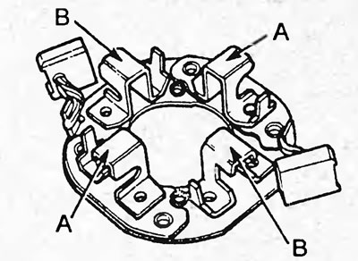
Denso (1.0 kW).
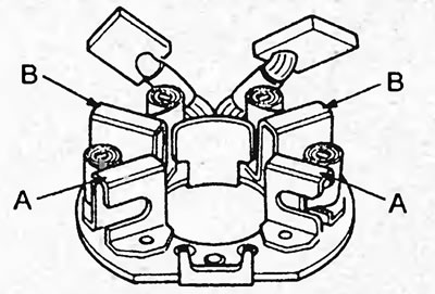
Mitsuba (1.0 kW).
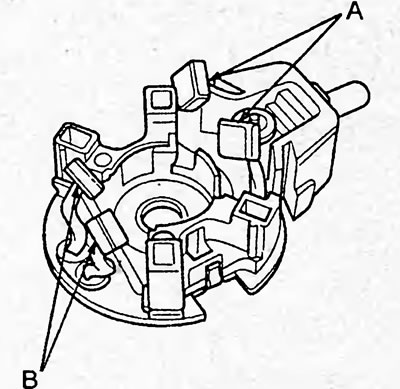
Mitsuba (0.8 kW).
Checking the gears
Inspect the working surfaces of the planetary gear teeth (A) and the driven gear (B) of the overrunning clutch for excessive wear or chips.
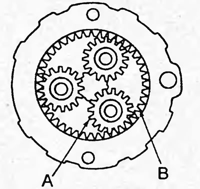
If there is wear or damage, replace the gears or the entire overrunning clutch assembly.
Checking the Mitsuba overrunning clutch (0.8 kW)
Check the overrunning clutch.
- While holding the planetary gears (A), turn the overrunning clutch shaft clockwise. Make sure that the planetary gears begin to rotate smoothly counterclockwise.
- While holding the planetary gears, turn the overrunning clutch shaft counterclockwise and make sure the shaft rotates smoothly.
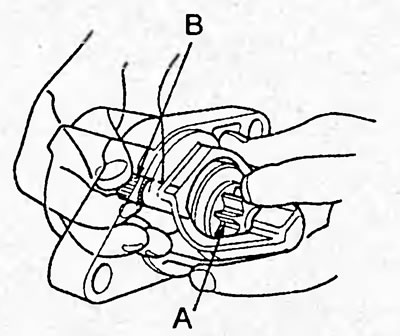
If the conditions are not met, replace the overrunning clutch.
Rest
1. Rotate the overrunning clutch (A) while holding the shaft stationary. Make sure that the clutch rotates smoothly.
2. Rotate the overrunning clutch (A) in both directions. Make sure that the clutch rotates in one direction and does not rotate in the other.
3. Check the overrunning clutch gear for chips and breakages. Replace the overrunning clutch if necessary.
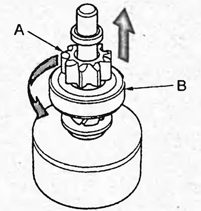
Denso (1.0 kW).
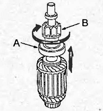
Denso (0.8 kW).
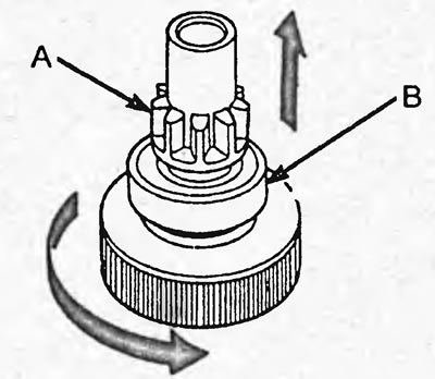
Mitsuba (1.0 kW).
If the conditions are not met, replace the overrunning clutch.
Checking the traction relay (except Mitsuba (0.8 kW))
1. Checking the pull-in winding of the traction relay.
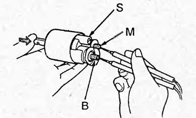
Check for continuity between the starter terminals "B", "S", "M" and the traction relay housing as shown in the figure below. Otherwise, replace the traction relay.
2. Checking the holding winding. Make sure there is conductivity between the starter terminals "M", "S" and the body. Otherwise, replace the traction relay.