
Disassembly and assembly (K20A)
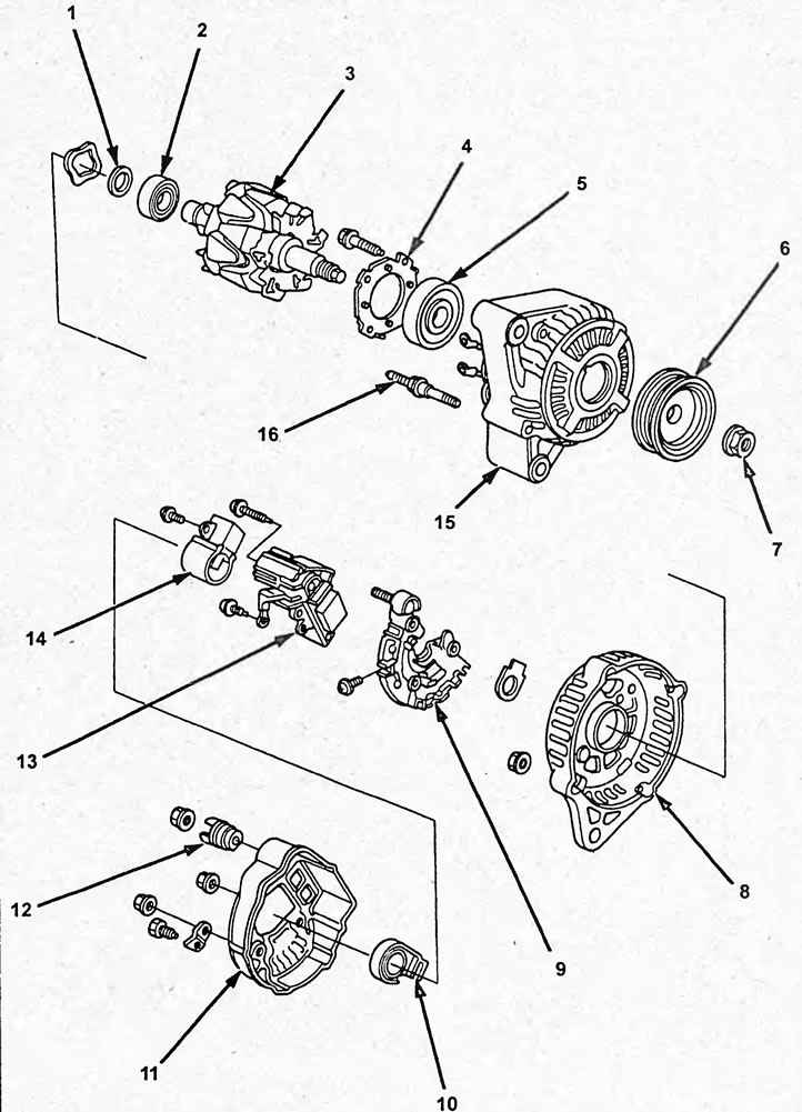
Disassembly and assembly of the generator (K20A).1 - bearing cover, 2 - rear bearing, 3 - rotor, 4 - front bearing holder, 5 - front bearing, 6 - generator drive pulley, 7 - generator drive pulley fastening nut, 8 - rear cover, 9 - rectifier unit, 10 - brush holder seal, 11 - cover, 12 - terminal insulator, 13 - voltage regulator, 14 - brush holder, 15 - front cover, 16 - tie bolt.
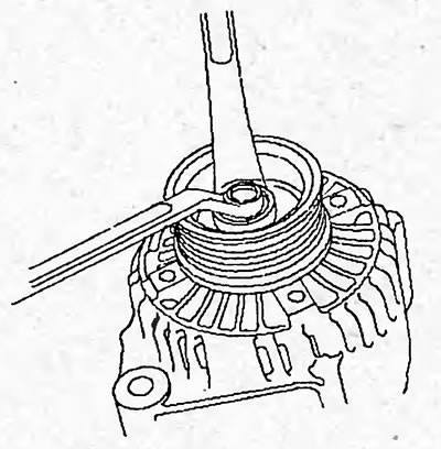
1. Replace the front bearing if necessary. Loosen the generator drive pulley mounting nut.
Tightening torque - 111 Nm
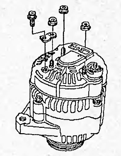
2. Loosen the three mounting nuts and the generator cover mounting screw, then remove the generator wire plate.
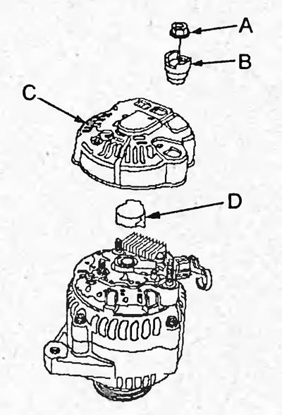
3. Loosen the nut (A), remove the insulator (B) of terminal "B", then remove the cover (C) and seal (D).
4. Remove the brush holder.
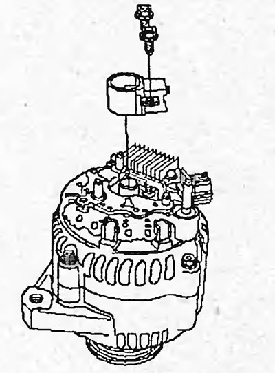
5. Remove the voltage regulator.
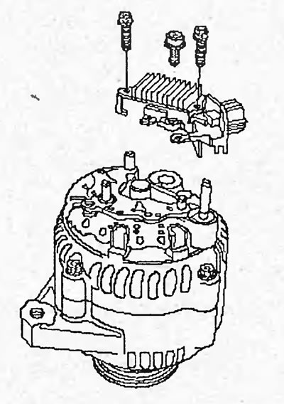
6. Loosen the four screws, remove the rectifier block (A) and seal (B).
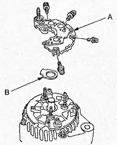
7. Unscrew the four nuts.
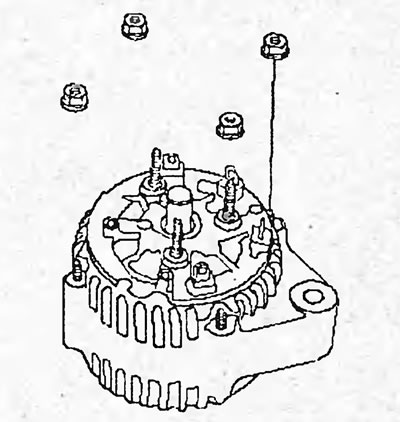
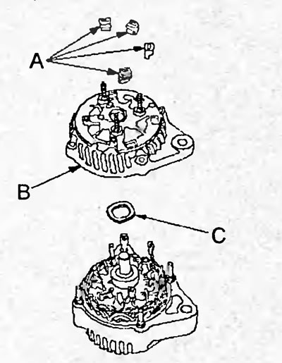
8. Remove the four insulators (A), the rear cover (B) and the washer (C).
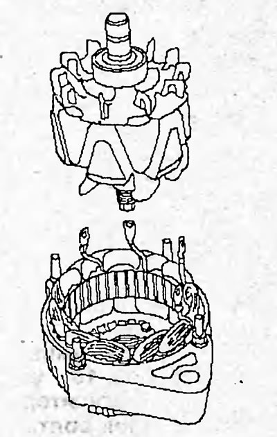
9. (If planned, replace the front bearing or rear bearing) Remove the rotor.
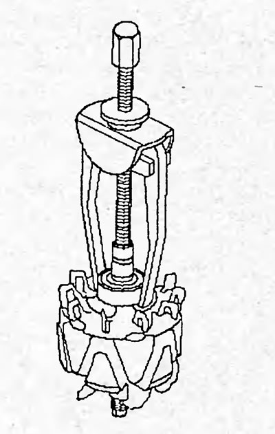
10. Remove the rear bearing using a special tool.
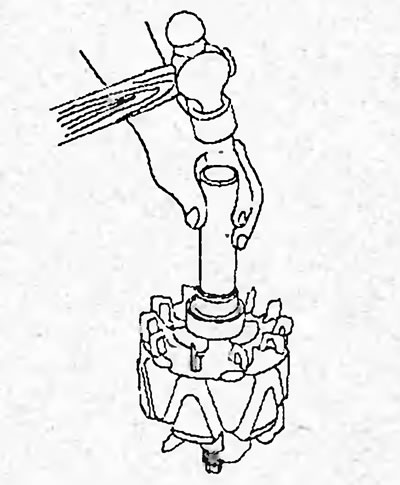
11. Using a hammer and special tool, install the new rear bearing onto the rotor shaft as shown in the figure.
12. Remove the front bearing retainer.
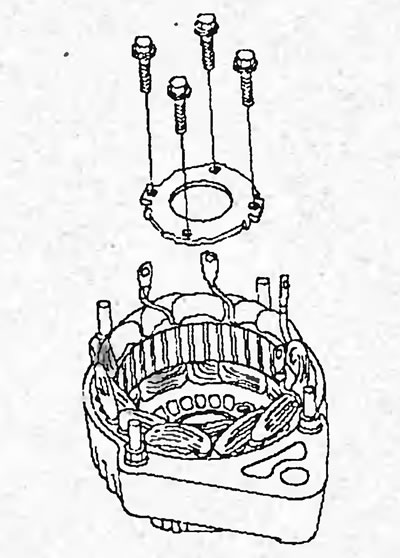
13. Place the stator on a flat surface and use a hammer and special tool to remove the front bearing.
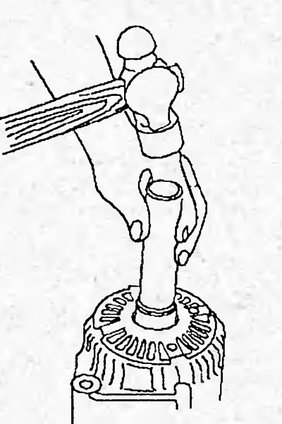
14. Using a hammer and special tool, install the new front bearing.
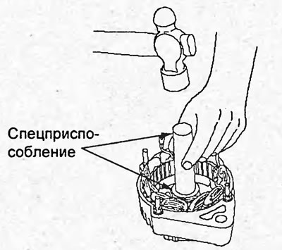
15. Assembly of parts is carried out in the reverse order of removal.
Note: Be careful not to allow engine oil or grease to come into contact with generator components.
Disassembly (D15B, D17A)
1. Unscrew the four mounting bolts.
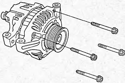
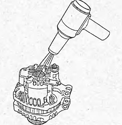
2. Heat the surface in the area of the rear bearing with warm air (50 - 60°) for 5 minutes.
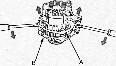
3. Insert a flat-head screwdriver between the rear (A) and front (B) generator covers and separate them as shown in the figure.
Caution: Do not damage the stator.
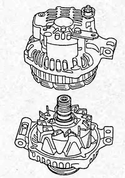
4. Remove the back cover.
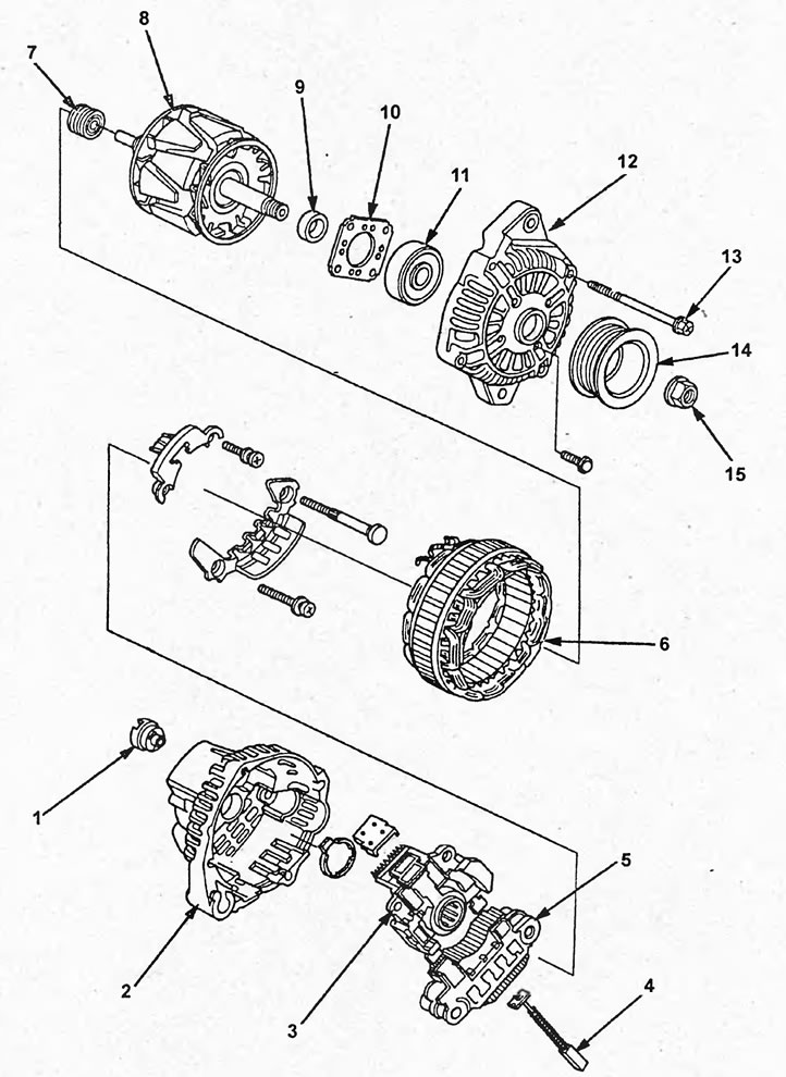
Disassembly and assembly of the generator (D15B, D17A). 1 - terminal insulator, 2 - rear cover, 3 - voltage regulator, 4 - brush, 5 - rectifier unit, 6 - stator, 7 - rear bearing, 8 - rotor, 9 - seal, 10 - front bearing holder, 11 - front bearing, 12 - front cover, 13 - tie bolt, 14 - generator pulley, 15 - generator pulley mounting nut.
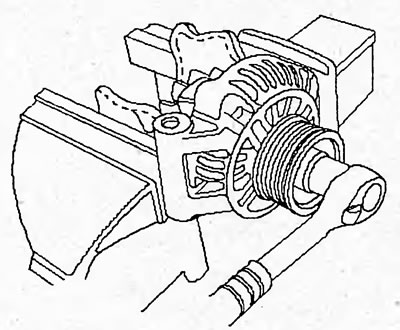
5. (If planned, replace the front bearing or rear bearing) Clamp the rotor assembly with the front cover in a vice, placing a rag underneath, and unscrew the generator pulley mounting nut.
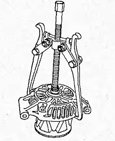
6. Remove the rotor using a special tool.
7. Check the smooth rotation of the rotor, the absence of damage to the rotor surface and slip rings.
Replace the generator if necessary.
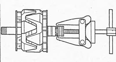
8. Remove the rear bearing using a special tool.
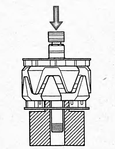
9. Using a press, install the new rear bearing. Apply force only to the outer surface of the bearing to avoid damaging it.
10. Remove the front bearing retainer.
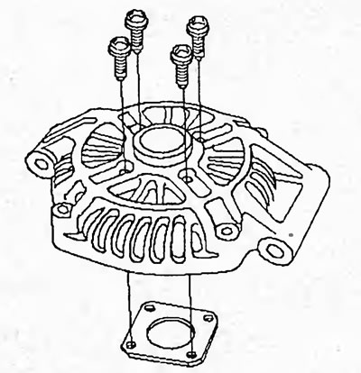
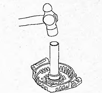
11. Fix the front cover in a vice and remove the front bearing using a hammer and special tool as shown in the figure.
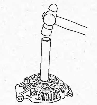
12. Using a hammer and special tool, install the new front bearing.
The article is based on information from the website www.hondabook.ru