
Contents: Diagnostics ⇊ Table. Electrical equipment control…⇊ Examination ⇊ Table. Checking the electrical…⇊ Table. Checking the electrical…⇊ Table. Checking the electrical…⇊ Table. Checking the electrical…⇊ Table. Checking the electrical…⇊ Table. Checking the electrical…⇊
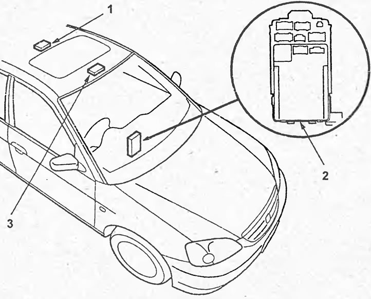
Location of electrical control system components (sedan). 1 - interior lighting lamp, 2 - Multiplex control unit, 3 - local lighting lamp.
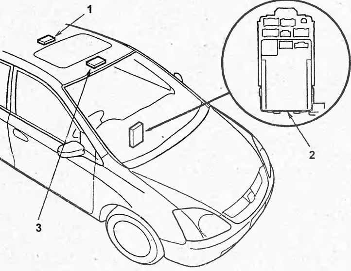
Location of electrical control system components (hatchback). 1 - interior lighting lamp, 2 - Multiplex control unit, 3 - local lighting lamp.
Diagnostics
Reading fault codes (mode 1)
1. Check fuses #9 (10A) (mounting block in the engine compartment) and No.10 (7.5 A) (mounting block in the cabin).
2. Remove the lower instrument panel trim.
3. Turn the ignition switch to the ON (II) position.
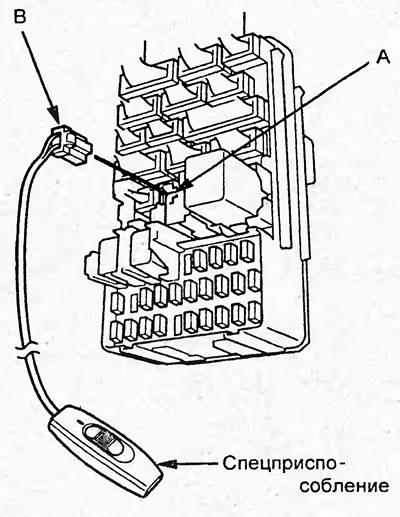
4. Connect the special tool (B) to the diagnostic connector of the Multiplex control unit (A) and wait for 5 seconds or more.
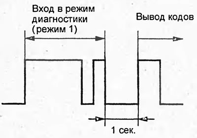
5. Check that the interior light and local light blink as shown in the figure.
If the lamps do not flash, turn the ignition switch to the "OFF" position and repeat the procedure for reading fault codes starting from step "3"
6. Read the fault codes for the interior light and the local light. The fault codes are listed in the table "Electrical Equipment Management System Fault Codes".
Table. Electrical equipment control system fault codes.
| Code | Malfunction |
| 1 | The Multiplex control unit does not receive a signal from the instrument cluster |
| 2 | The Multiplex control unit does not receive a signal from the powertrain control unit |
| 3 | Internal failure of the Multiplex control unit |
| 5 | The instrument cluster does not receive a signal from the Multiplex control unit and the powertrain control unit |
| 6 | The powertrain control unit does not receive a signal from the Multiplex control unit and instrument cluster |
7. To exit mode 1, disconnect the special tool from the diagnostic connector of the Multiplex control unit and wait 10 seconds or turn the ignition switch to the "OFF" position.
Checking circuits to components (mode 2)
1. To switch to mode 2, while in mode 1, disconnect the special tool from the diagnostic connector of the Multiplex control unit for 10 seconds and reconnect it. Make sure that the interior light and local lighting lamp flash as shown in the figure.
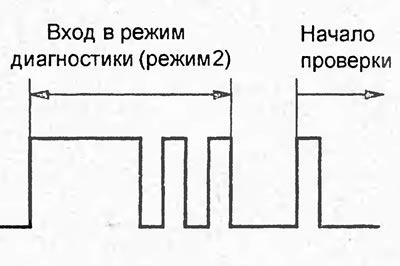
2. The self-diagnostic system will check the circuits to the following components:
- driver seat belt sensor;
- pressure switch;
- central locking remote control unit;
- parking brake switch;
- "ABS" indicator;
- driver's door lock switch;
- electric windshield washer pump;
- windshield wiper motor;
- driver's door limit switch;
- front passenger door limit switch;
- rear left door limit switch;
- rear right door limit switch;
- key presence sensor in ignition switch;
- limit switch in the trunk lid lock (sedan);
- limit switch in the rear door lock (hatchback).
If the circuit is OK, the interior light will flash once.
If the circuit is faulty, the interior light will not flash.
3. To exit mode 2, disconnect the special tool from the diagnostic connector of the electrical equipment control unit and wait 10 seconds or turn the ignition switch to the "OFF" position.
Examination
1. Remove the lower instrument panel trim.
2. Disconnect the connectors.
3. Check fuses #10 (7.5A), #8 (7.5A) and #16 (20A) (mounting block in the engine compartment).
4. Check the electrical equipment control system according to the tables "Checking the electrical equipment control system".
Table. Checking the electrical equipment control system.
| Conclusion | Wire color | Verification conditions | In good condition | Possible cause/location of malfunction |
| J2 | W/R | Constantly | At the terminal "J2" the battery voltage | -Fuse No.9 (10 A) (mounting block in the engine compartment) -Broken wire |
| J4 | IN | Constantly | Conductivity between terminal "J4" and ground | - Poor ground contact (G301) - Broken wire |
| Y6 | IN | Constantly | Conductivity between terminal "Y6" and ground | -Bad ground contact (G501 *1 or G502²) - Wire break |
| Q3 | G | The driver's door is open | Conductivity between terminal "Q3" and ground | - Driver's door limit switch - Wire break |
| Q4 | Lg/R | The front passenger door is open | Conductivity between terminal "Q4" and ground | -Front passenger door switch -Wire break |
| Q2 | G/W | Rear right or rear left door open | Conductivity between terminal "Q2" and ground | -Rear right or rear left door limit switch -Wire break |
| C8 | G/R | Parking brake on | Conductivity between terminal "C8" and ground | -Parking brake position sensor -Wire break |
| F1 | G/R | Conductivity between terminal "F1" and ground | ||
| Q6 | BI/R | The driver's seat belt is not inserted into the buckle | Conductivity between terminal "Q5" and ground | -Bad ground connection (G551) -Driver seat belt sensor -Broken wire |
| R18 | R | Trunk lid*1 or rear door 2 is open | Conductivity between terminal "P18" and ground | -Bad ground contact (G601*1 or G553²) Limit switch in trunk lid lock 1 - Limit switch in rear door lock 2 - Wire break |
| X5 | R/W | The key is inserted into the ignition switch | Conductivity between terminal "X5" and ground | -Bad ground contact (G401) -Key in ignition switch sensor -Broken wire |
| 07 | G/R | Interior light switch in "MIDDIE" position | At the terminal "07" the battery voltage | -Fuse No.3 (7.5 A) (mounting block in the engine compartment) -Interior lighting lamp -Broken wire |
| C11 | Bl | Light switch in the "ON" position | At the terminal "C11" the voltage of the battery | - Fuse No.2 (15 A) (mounting block in the engine compartment) - Side light relay - Light switch - Wire break |
| F8 | G/R | Brake fluid level below the "MIN" mark | At the "F8" terminal the battery voltage | -Poor ground connection (G201) -Low brake fluid level sensor |
| Y1 | Br/Y | Ignition switch in the "ON" position (II) | Conductivity between terminal "Y1" and ground | Wire break |
| E10* | Y | Constantly | At the "E10" terminal, the voltage is 3 - 8 V in "standby mode" or the battery voltage in "operating mode" | Wire break |
| K10* | W/G | At the "E10" terminal, the voltage is 3 - 8 V in "standby mode" or the battery voltage in "operating mode" | Wire break |
- - connect the connector before testing,
- *1 - sedan,
- *2 - hatchback.
Table. Checking the electrical equipment control system (ignition key interlock system).
| Conclusion | Wire color | Verification conditions | In good condition | Possible cause/location of malfunction |
| D10 | BI/B | Automatic transmission selector in position "P" | Conductivity between pin "D10" and ground | -Bad ground contact (G101) -Automatic transmission selector position sensor -Broken wire |
| X1 | W/R | Ignition switch in the "ACC" position | Conductivity between terminal "X1" and ground | - Poor ground contact (G401) - Broken wire |
Table. Checking the electrical equipment control system (automatic transmission selector lock system).
| Conclusion | Wire color | Verification conditions | In good condition | Possible cause/location of malfunction |
| E13*2 | W/Y | Automatic transmission selector in position "P", ignition switch in position "ON" (II), brake pedal pressed | At the terminal "E13" the battery voltage | - Powertrain control unit - Wire break |
| O5 | W/B | The brake pedal is pressed | At the "O5" terminal, the battery voltage | -Fuse No.7 (15 A) (mounting block in the engine compartment) - Brake light switch - Broken wire |
| D10 | BI/B | Automatic transmission selector in position "P" | At the "D10" terminal the battery voltage | -Bad ground contact (G101) -Automatic transmission selector position sensor -Broken wire |
| G10 | B/R | Automatic transmission selector in position "N" | Conductivity between the "GW" terminal and ground | -Bad ground contact (G101) -Automatic transmission selector position sensor -Broken wire |
| R3 | Y/B | Ignition switch in the "ON" position (II)*1 or "ACC" (I)*2 | At the "D4" terminal the battery voltage | -Fuse No.10 (7.5 A)*1 or No.8 (7.5 A) (mounting block in the cabin) - Selector lock solenoid valve - Wire break |
- *1 - sedan
- *2 - hatchback.
Table. Checking the electrical equipment control system (central locking).
| Conclusion | Wire color | Verification conditions | In good condition | Possible cause/location of malfunction |
| J7 | W | Constantly | At the terminal "J7" the battery voltage | -Fuse No.16 (20 A) (mounting block in the engine compartment) -Broken wire |
| X5 | R/W | The key is inserted into the ignition switch | Conductivity between terminal "X5" and ground | -Bad ground contact (G401) -Key in ignition switch sensor -Broken wire |
| Q3 | G | The driver's door is open | Conductivity between terminal "Q3" and ground | - Driver's door limit switch - Wire break |
| Q4 | Lg/R | The front passenger door is open | Conductivity between terminal "Q4" and ground | -Front passenger door limit switch -Wire break |
| Q2 | G/W | Rear right or rear left door open | Conductivity between terminal "Q2" and ground | -Rear right or rear left door limit switch -Wire break |
| R18 | R | Trunk lid 1 or rear door 2 is open | Conductivity between terminal "P18" and ground | -Bad ground contact (G601*1 or G553 *2) - Limit switch in the trunk lid lock 1 - Limit switch in the rear door lock 2 - Wire break |
| Y7 | W/B | Driver's door lock switch in the "UNLOCK" position | Conductivity between terminal "Y7" and ground | -Bad ground connection (G501) -Driver's door lock switch -Broken wire |
| Y8 | Y/R | Driver's door lock switch in the "LOCK" position | Conductivity between terminal "Y8" and ground | |
| M6 | Y/B | The battery is connected to terminals "M6" (+) and "M9" (-) | Driver's door lock is activated when battery is connected | - Driver's door lock electric drive - Wire break |
| M9 | Y/B*1 Y*2 | |||
| M7 | Y/B | The battery is connected to terminals "M7" (+) and "M8" (-) | The front passenger door lock is activated when the battery is connected | - Electric drive of the front passenger door lock - Broken wire |
| M8 | Y | |||
| R17 | Y/B | The battery is connected to terminals "P17" (+) and "P16" (-) | Rear side door locks and rear door/trunk lid lock operate when battery is connected | - Electric drives of rear side door locks - Electric drive of trunk lid lock - Electric drive of rear door lock 2 - Wire break |
| R16 | Y |
- *1 - sedan
- *2 - hatchback.
Table. Checking the electrical equipment control system (interior lighting system).
| Conclusion | Color - wires | Verification conditions | In good condition | Possible cause/location of malfunction |
| X5 | R/W | The key is inserted into the ignition switch | Conductivity between terminal "X5" and ground | -Bad ground contact (G401) -Key in ignition switch sensor -Broken wire |
| Q3 | G | The driver's door is open | Conductivity between terminal "Q3" and ground | - Driver's door limit switch - Wire break |
| Q4 | Lg/R | The front passenger door is open | Conductivity between terminal "Q4" and ground | -Front passenger door limit switch -Wire break |
| Q2 | G/W | Rear right or rear left door open | Conductivity between terminal "Q2" and ground | - Rear right or rear left door limit switch |
| R18 | R | Trunk lid*1 or the back door *2 open | Conductivity between terminal "P18" and ground | -Bad ground contact (G601*1or G553 Limit switch in the trunk lid lock*1 - Limit switch in the rear door lock*2 |
| Y8 | Y/R | Driver's door lock switch in the "LOCK" position | Conductivity between terminal "Y8" and ground | -Bad ground connection (G501) -Driver's door lock switch |
| 07 | G/R | Interior light switch in "MIDDLE" position | At the terminal "07" the battery voltage | - Fuse No.3 (7.5 A) (mounting block in the engine compartment) - Interior lighting lamp |
- *1 - sedan
- *2 - hatchback.
Table. Checking the electrical equipment control system (windshield wiper interval control system).
| Conclusion | Wire color | Verification conditions | In good condition | Possible cause/location of malfunction |
| B1 | W/BI | Ignition switch in the "ON" (II) position, windshield wiper switch in the "ON" position | At the terminal "B1" the battery voltage | -Fuse No.20 (20 A) (mounting block in the cabin) - Windshield wiper and washer control switch |
| X7 | BI/B | Ignition switch in the "ON" (II) position, windshield wiper switch in the "INT" position | At the terminal "X7" the battery voltage | -Fuse No.20 (20 A) (mounting block in the cabin) -Windshield wiper and washer control switch |
| B6 | BI/R | Ignition switch in the "ON" position (II) | At the terminal "B6" the voltage of the battery | -Fuse No.20 (20 A) (mounting block in the cabin) -Windshield wiper and washer control switch -Windshield wiper motor |
| G7 | BI/W | Ignition switch in the "ON" position (II) | At the "G7" terminal, the battery voltage | -Fuse No.20 (20 A) (mounting block in the cabin) -Windshield wiper and washer control switch -Windshield wiper motor |
| X4 | G/W | Rotate the wiper interval control | The resistance between terminals "X4" and "X3" varies within the range of 0-30 kOhm | - Windshield washer control switch - Wire break |
| I don't know | G/0 |
If a malfunction is detected, check the components listed in the "Possible Cause/Location of Malfunction" section of the table.
If the components are OK but the system does not work, replace the fuse box (in the passenger compartment) (electrical equipment control unit).
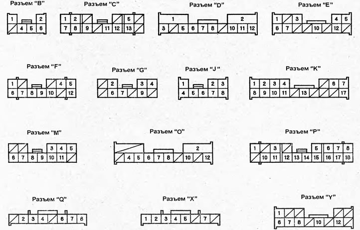
Connectors (from the wiring harness side)
1) не гаснет лампочка ручного тормоза (колодки толстые, уровень торм.жидкости в норме)
2) На первой скорости не работают дворники лобового стекла (остальные работают)
3) Кое как брызгает жидкость на лобовое стекло.
После скидывания клеммы аккумулятора всё это заработало : дворники в 1 режиме и погасла лампочка ручника на панели.
Потом проехался и снова всё вернулось.
Сделал вывод что не работает блок мультиплекс.
Остался вопрос что за спецприспособление подключается к диагностическому разъёму мультиплекса?