
2. Compare the measured values with those given in the table "Voltage at the terminals of the ABS control unit". If necessary, repair or replace the faulty element.
Table. ABS system fault codes.
| Fault code | Malfunction | Possible location of the malfunction |
| 11 | Open or short circuit in the front right wheel speed sensor circuit | Wheel Speed Sensor Wheel Speed Sensor Rotor Wiring |
| 12 | Incorrect signal (signal distortion or sudden change in signal) front right wheel speed sensor | |
| 13 | Open or short circuit in the front left wheel speed sensor circuit | |
| 14 | Incorrect signal (signal distortion or sudden change in signal) front left wheel speed sensor | |
| 15 | Open or short circuit in the rear right wheel speed sensor circuit | |
| 16 | Incorrect signal (signal distortion or sudden change in signal) rear right wheel speed sensor | |
| 17 | Open or short circuit in the rear left wheel speed sensor circuit | |
| 18 | Incorrect signal (signal distortion or sudden change in signal) rear left wheel speed sensor | |
| 21 | Front right wheel speed sensor rotor malfunction | |
| 22 | Front left wheel speed sensor rotor malfunction | Wheel speed sensor rotor |
| 23 | Rear right wheel speed sensor rotor malfunction | |
| 24 | Rear left wheel speed sensor rotor malfunction | |
| 31 | Malfunction of the electromagnetic valve of the pressure modulator | Solenoid Valve ABS Control Unit Wiring |
| 32 | ||
| 33 | ||
| 34 | ||
| 35 | ||
| 36 | ||
| 37 | ||
| 38 | ||
| 41 | Front right locks up when ABS system is operating | Wheel Speed Sensor Wheel Speed Sensor Rotor ABS Control Unit Pressure Modulator Wiring |
| 42 | Front left locks up when ABS system is operating | |
| 43 | Rear right locks when ABS system is operating | |
| 44 | Rear left locks up when ABS system is operating | |
| 51 | ABS pump motor lockout | Fuse #10 in the fuse box (in the engine compartment) Pressure Modulator ABS Control Unit Wiring |
| 52 | ABS pump motor does not turn on | ABS pump motor ABS control unit Fuse #10 in the fuse box (in the engine compartment) Wiring |
| 53 | ABS pump motor does not turn off (works constantly) | ABS pump motor ABS control unit |
| 54 | ABS Fail Safe Relay Malfunction | Pressure Modulator ABS Control Unit Wiring |
| 61 | Low voltage on emergency mode relay | Power Supply Wiring |
| 62 | High voltage on emergency mode relay | |
| 71 | The wheels installed on the car have different sizes | Wheels of different sizes are installed. Tire pressure is not the same |
| 81 | ABS control unit malfunction | ABS control unit |
Table. Voltage at the terminals of the ABS control unit.
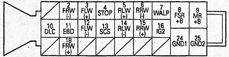
| Conclusion | Signal | Conclusions for verification | Verification conditions | Voltage, V |
| 2 | FRW (-) | 2-18 | The front right wheel rotates at 1 rpm | 0.053 V or more (AC) |
| 3 | FLW (+) | 3-12 | The front left wheel rotates at 1 rpm | 0.053 V or more (AC) |
| 4 | STOP | 4-GND | The brake pedal is pressed | VB |
| The brake pedal is not pressed | Less than 0.3 V | |||
| 5 | RLW (+) | 5-14 | The rear left wheel rotates at 1 rpm | 0.053 V or more (AC) |
| 6 | RRW (-) | 6-15 | The rear right wheel rotates at 1 rpm | 0.053 V or more (AC) |
| 7 | WALP | 7-GND | Ignition is on | ≈6 V |
| 8 | FSR+B | 8 - GND | Constantly | VB |
| 9 | MR+B | 9-GND | Constantly | VB |
| 10 | DLC | - | - | - |
| 11 | EBD | 11 - GND | Parking brake on | Less than 0.3 V |
| The parking brake is released | VB | |||
| 12 | FLW (-) | 12-3 | The front left wheel rotates at 1 rpm | 0.053 V or more (AC) |
| 13 | SCS | - | - | - |
| 14 | RLW (-) | 14-5 | The rear left wheel rotates at 1 rpm | 0.053 V or more (AC) |
| 15 | RRW (+) | 15-6 | The rear right wheel rotates at 1 rpm | 0.053 V or more (AC) |
| 16 | IG2 | 16-GND | Ignition is on | VB |
| 18 | FRW (-) | 18-2 | The front right wheel rotates at 1 rpm | 0.053 V or more (AC) |
| 24 | GND1 | - | - | - |
| 25 | GND2 | - | - | - |
Note:
- AC - measurements are taken in alternating current mode;
- VB - battery voltage.
[Based on materials from the website: HondaBook.ru]