Gap
1. Remove the connecting rod cover and liner.
2. Wipe the main journal and liner with a clean rag
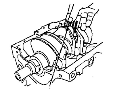
3. Place the measuring plate along the crankpin.
4. Install the liner and cover and tighten the nuts.
Torque
Engines А16А2.В16А4.В16А5,В16А6:
- Microdistrict = 40 Nm
Other engines:
- Microdistrict = 31 Nm
Note: Do not rotate the crankshaft while checking.
5. Remove the connecting rod cap and liner and measure the widest part of the compressed plate.
Oil gap between the journal and the connecting rod bearing:
Engines A16A2, B16A4, B16A5, B16A6:
- Standard value: 0.032-0.050 mm
- Operational value: 0.06 mm
Other engines:
- Standard value: 0.020-0.038 mm
- Operational values: 0.05 mm
6. If the size of the compressed plate is too wide or too narrow, remove the liners and install a new set of liners with the corresponding color code (select the color as indicated in the table on the right) and re-measure the gap.
Attention. Do not file or scrape bearings or caps, or use expansion joints to adjust the clearance.
7, If measurements show that the gap does not meet the required values, use the next larger or smaller size bushing (color indicated above or below given) and measure the gap again.
Note: If the correct clearance cannot be obtained using a suitable larger or smaller bearing, replace the crankshaft and re-measure the clearance.
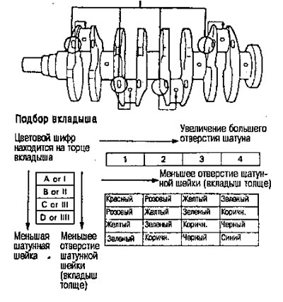
Selection
Attention. If the codes cannot be seen due to dirt and dust accumulation, do not remove them with a wire brush or scraper. Clean them only with solvent or powder.
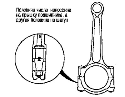
Location of codes on the connecting rod
The numbers are marked on the side of each connecting rod as a code for the size of the larger hole. Use them and the letters printed on the crankshaft (crankpin size codes) to select the correct inserts.
Location of connecting rod journal codes (letters)