
2. Wipe the connecting rod journal on the crankshaft and the bearing shell with a clean cloth.
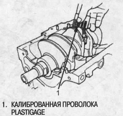
3. Lay a length of gauged Plastigage wire across the crankpins.
4. Reinstall bearing shell and bearing cap and tighten nuts to specification. Tightening torque: 31 Nm (3.2 kgf/m) /
Note: Do not rotate the crankshaft while checking.
5. Remove the cap and bearing shell and measure the widest part of the flattened wire.
Oil clearance between connecting rod bearing and journal:
- Standard (new): 0.020-0.038mm
- Redistribution: 0.05 mm
6. If the wire flattens too wide or too narrow, remove the top bearing shell, install a new bearing assembly with the same color code (choose color as below) and recheck the clearance.
Bearing marking
The color marking is located on the edge of the bearing.
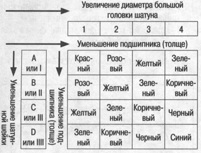
7. If the wire clearance is still incorrect, change to the next larger or smaller size bearing (with color coding before or after the one you have chosen) and repeat the clearance check again.
Note: If the required clearance cannot be obtained by substituting the next larger or smaller size bearings, respectively, replace the crankshaft and start over.
The location of the markings on the connecting rods
Note: If the marking cannot be disassembled due to accumulation of dirt or dust, do not scrape it with a wire brush or scraper. Clean them only with solvent or detergent.
Numbers are stamped on the end surface of the connecting rods, which indicate the diameter of the large connecting rod head. Use these numbers, as well as the letters stamped on the crankshaft (crankpin diameter marking) to select a bearing with the required size.
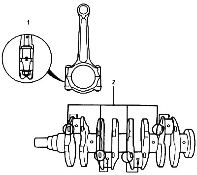
1. One half of the number is stamped on the bearing cap, the other half is stamped on the connecting rod.
2. The location of the markings of the connecting rod journals (letters)