Checking the oil clearance of the connecting rod bearings
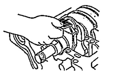
1. Clean the crankshaft journal and the connecting rod bearing shells.
2. Place plastic gauges on the crankpins.
3. Install the connecting rod caps.
Torque:
- Stage 1 - 10 Nm
- Stage 2 - 90°
Note: Do not rotate the crankshaft.
4. Remove covers of rods with loose leaves. Measure the thickness of the gauge at its widest point.
Clearance between connecting rod bearing shell and crankshaft journal:
- nominal - 0.020 - 0.038 mm
- maximum - 0.050 mm
If the clearance is not correct, install a new set of bearing shells with the same color code and recheck the clearance.
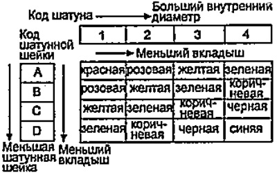
If the clearance is still not within specification, replace the bearings with larger or smaller bearings (color labels are shown below). Check oil clearance. If the clearance is still not correct, replace the crankshaft and check the clearance again.
Selection of connecting rod bearing shells
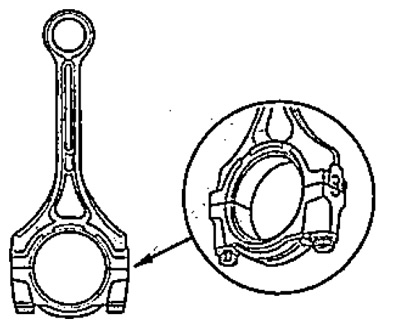
1. Check all connecting rods for chips and burn marks.
2. Cranks come in four size groups (increase in nominal diameter at 0 to 0.024 mm in increments of 0.006 mm). Number (1, 2, 3 or 4) size group is stamped on the end of the connecting rod bearing caps. You can find different combinations of size groups on different engines.
If you cannot read the code due to deposits, do not clean the marks with a wire brush, use a solvent.
- Nominal inner diameter - 43 mm
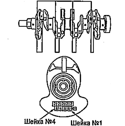
3. The crankpin size code is stamped on the crankshaft.
4. Using the code of the connecting rod and connecting rod neck, using the table, select the necessary liners of connecting rod bearings.