
Contents: Gap ⇊ Selection ⇊
Gap
1. To check the oil clearance between the main journal and the bearing, remove the main caps and liners.
2. Clean the main journal and bearing shell with a clean cloth.
3. Place one plastic measuring plate across each main journal.
Note: If the engine is installed on the vehicle when measuring the gap between the cover liner and the main journal, the weight of the crankshaft and flywheel will affect the deformation of the measuring plate and we will get an incorrect result. To get an accurate reading, place a jack under the crankshaft journal counterweight and check the gap on this journal only.
4. Install the liners and covers and tighten the bolts.
stage 1: Mkr. = 25 Nm
Final stage:
Engines B16A2, B16A4, B16A5, B16A6:
- Mkr. = 76 Nm
Engines D15Y4, D16Y5, D16Y6, D16Y7, D16Y8, D16Y9, D16Z6:
- Mkr. = 51 Nm
Engines D14A3, D14A4, D15Z1, D15Z4, D15Z5, D15Z6, D15Z7, D13B2, D15B2, D15B7:
- Mkr. = 44 Nm
Note: Do not rotate the crankshaft during inspection.
5. Remove the covers and liners and measure the widest part of the warped measuring plates.
Oil clearance between main bearing and journal:
Engines B16A2, B16A4, B16A5, B16A6:
Default value:
- Necks #1, 2, 4, 5: 0.024-0.042 mm
- Neck #3: 0.030-0.048 mm
Operational value: 0.06 mm
Other engines:
Default value:
- Necks #1, 5: 0.018-6.036 mm
- Necks #2, 3, 4: 0.024-0.042 mm
Operational value: 0.05 mm
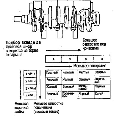
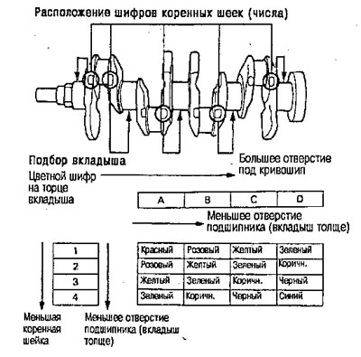
6. If the size of the deformed plate is too wide or too narrow, (remove the engine if it is still in the engine), remove the crankshaft and remove the upper bearing shell. Install a new one, selecting the shell of the corresponding color code (select color as shown on next page) and check the gap again.
Caution: Do not file, shim, or scrape bearings or caps to adjust clearance.
7. If the warped plate shows clearance still not optimal, use larger or smaller inserts (color choosing higher or lower than used) and measure again.
Note: If the required clearance cannot be obtained using larger or smaller bearing shells, replace the crankshaft and repeat the measurements again.
Selection
Caution: If the markings are illegible due to dirt and dust accumulation, do not remove them with a wire brush or scraper. Clean them only with solvent or powder.
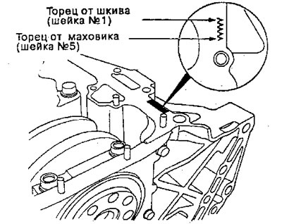
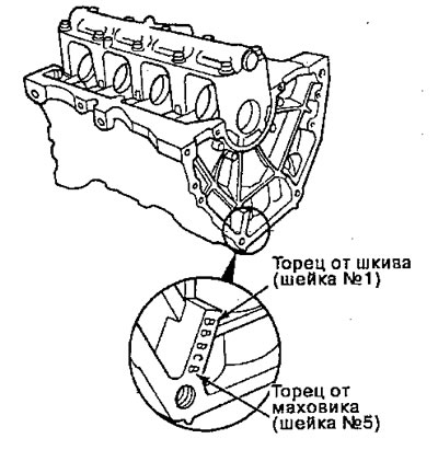
Location of crankshaft hole markings
Engines B16A2, B16A4, B15A5, B16A6:
Letters, applied to the bottom plane of the block, as a code for the size of each of the 5 holes for the main journals. Use these and the numbers or stripes applied to the crank (neck size code) to select the correct inserts.
 |
 |
Other engines:
Letters are stamped on the bottom of the block as a code for the size of each of the 5 main journal bores. Use these and the numbers or stripes printed on the crankshaft (neck size code) to select the correct inserts.
 |
 |
Material obtained from the website: hondabook