
Rectifier test
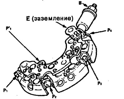
Nippon dense:
Note: Diodes are designed to allow current to pass in one direction and block it in the other. Since the generator rectifier consists of eight diodes (four pairs), each of the diodes should be tested for continuity in both directions using an ohmmeter designed for diode testing. In total, 16 measurements need to be performed.
1. Check continuity in each direction between:
- Contacts B and R.
- Contacts E (grounding) and R.
All diodes must conduct in one direction only.
2. If any of the diodes are faulty, replace the rectifier assembly, (diodes are not available separately.)
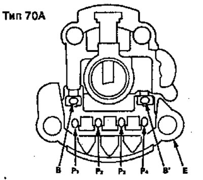
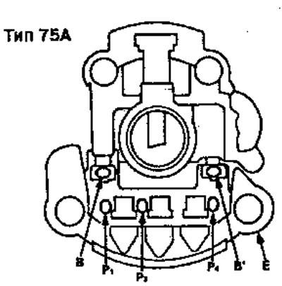
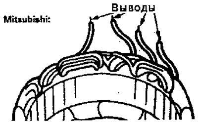
Mitsubishi:
Note: Diodes are designed to allow current to flow in one direction and block it in the other. Since the generator rectifier consists of nine (eleven) diodes, each diode must be tested for continuity in both directions using an ohmmeter designed for diode testing. In total, you need to complete 18 (22) measurements, 1.
Check continuity in each direction between:
- Contacts B and R.
- Contacts B1 and P (except P2)
- Contacts E (grounding) and R.
All diodes must conduct in one direction only.
2. If any of the diodes are faulty, replace the rectifier assembly, (diodes are not available separately.)
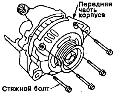
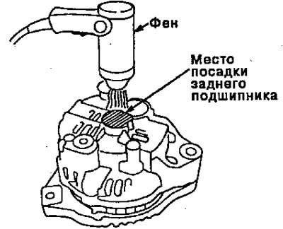
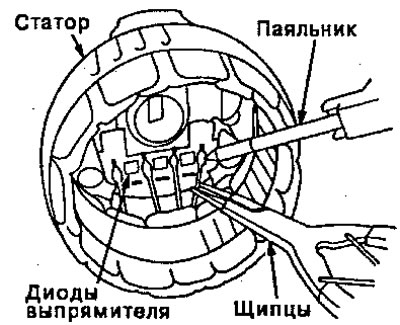
Removing the rectifier (Mitsubishi)
1. Remove the four pinch bolts.
2. Heat the rear bearing seat with a 1000 W hairdryer for 5 minutes (50-60°С).
3. Separate the back of the case from the front of the case by inserting flat-tip screwdrivers into the holes and pushing them apart.
Note: Be careful not to damage the stator with the tip of the screwdriver
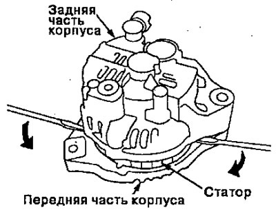
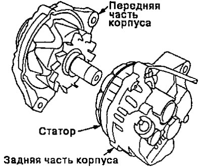
4. Separate the back and front parts of the case. NOTE: When separating the front and rear housings, the stator remains on the rear of the housing.
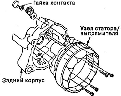
5. Separate the rear housing from the stator/rectifier assembly by removing the four screws and terminal nut.
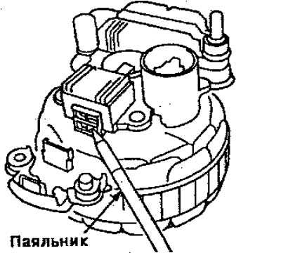
6. Unsolder the rectifier from the stator leads.
- To avoid damage to the diodes from high temperature, press the leads with pliers to remove (take off) high temperature and use the soldering iron for as long as necessary to separate the leads from the rectifier. (No longer).
- Use a 100 W soldering iron.
7. Install the new rectifier in the reverse order of removal.
- Use the soldering iron as much as necessary to ensure a good connection so that the heat does not damage the diodes.
- Use rosin type flux, otherwise the junction joints will corrode.
Inspection of generator brushes
Nippondenso:
1. Remove the cover, then remove the brush retainer by removing its two screws.
2. Measure the length of the brushes using a caliper.
Generator brush length:
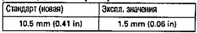
3. If the brush length is shorter than specified, replace the alternator brush assembly.
Mitsubishi:
1. Separate the front housing from the rear housing.
2. Separate the rear housing from the rectifier/stator assembly by removing the four screws and terminal nut from the rear housing.
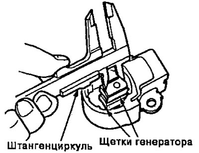
3. Measure the length of the brushes with a caliper.
Alternator brush length
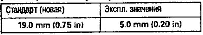
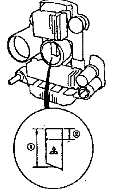
4. If the length of the brushes is shorter than specified in the operating values, replace them.
Checking motor brush contacts
1. Check the resistance between the brush contacts.
Resistance should be 1.8-3.0 Ohm
- If the resistance is within specification, proceed to step 2.
- If resistance is not within specification, replace alternator.
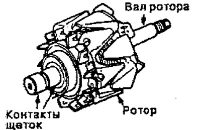
2. Check that there is no continuity between the brush contacts and the rotor or rotor shaft.
3. If the rotor fails each of the continuity tests, replace the alternator.
Stator check
1. Check that there is continuity between each pair of terminals.
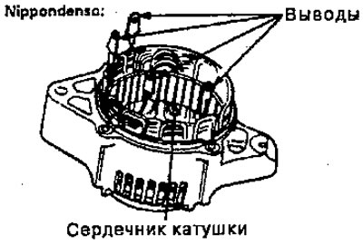
2. Check that there is no continuity between each terminal and the coil core.
3. If the coil does not pass each of the tests, replace the generator.
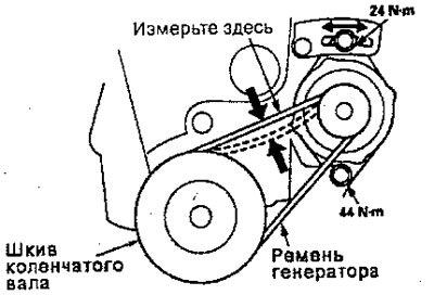
Inspecting and adjusting the alternator belt
Deviation measurement method:
Apply a force of 98 N (10 kgf) and measure the deviation between the generator and crankshaft pulleys.
Deviation: 7 -10mm
Note: new belt (who worked no more than five minutes), the deviation should be 5.0-8.0mm when first measured. If the belt is worn or damaged, replace it.
If adjustment is necessary:
1. Loosen the lower fastening nut and the upper fastening bolt.
2. Move the generator to obtain the required belt tension, then tighten the upper mounting bolt and lower mounting nut to the nominal torque.
3. Check the belt tension again.