
Upper arm
2. Remove the bolt securing the upper arm to the rail (see fig. 14.12).
3. Remove the bolts securing the upper arm to the body and dismantle the arm.
4. Inspect the lever bushings for wear and cracking. If they are bad, press them out and install new ones.
5. Installation is made in the return to removal order.
Lower arm
6. Turn away a bolt of fastening of the stabilizer to the bottom lever.
7. Turn away a bolt of fastening of the bottom lever to longitudinal.
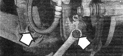
Pic. 23.7 Fastening the lower arm to the longitudinal and mounting the shock absorber to the lower arm
8. Turn away a bolt of fastening of the shock-absorber to the bottom lever.
9. Turn away a nut of a bolt of fastening of the lower arm to the case and remove the lower arm.
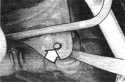
Pic. 23.9 Bolt and nut securing the lower arm to the body
10. Inspect the lever bushings for wear and cracks. If the bushings are not suitable, press them out and install new ones.
11. Install in reverse order Compensation lever.
12. Remove the fastening of the compensation lever to the trailing arm (see fig. 14.12).
13. Remove the lever attachment to the body and dismantle the lever.
14. Inspect the lever bushings for wear and cracks. If they are bad, press them out and install new ones.
15. Installation is made in the return to removal order. Longitudinal lever.
16. Disconnect brake hoses from brakes and muffle them. Remove the brake drums or brake calipers. Disconnect the parking brake cable (see chapter 9).
17. Remove the rear hub (see section 15).
18. Remove the brake drum support shield.
19. Remove the upper, lower and compensation arms from the guide arm (see above).
20. Remove the guide arm bushing mounting bolts and dismantle the arm.
21. Inspect the lever bushing. If it is worn out, press it out and replace it with a new one.
22. Installation is carried out in the reverse order of removal.