
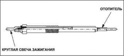
See the System Diagram for a functional diagram of this system. Glow plug control relay
Controls when and how long the glow plug is activated during engine start according to the coolant temperature.
Fuel filter water gauge
This water level indicator is installed in the fuel filter. It detects the water level in the fuel filter.
 | 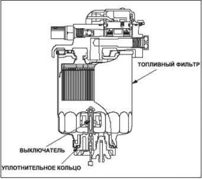 |
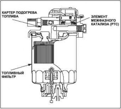
Fuel heating
The fuel heater is built into the fuel filter.
The system prevents deposition of wax in the fuel when the temperature drops to a critical value.
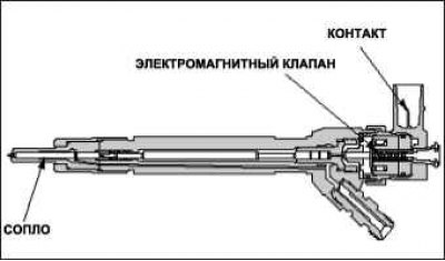
Fuel injector
This model has a compact and economical injector control solenoid valve. Each fuel injector is assigned its own IQA number, which allows more accurate fuel injection, thanks to injection control on each injector, depending on the injection system performance.
Rail pressure sensor (FRP)
The FRP sensor detects the fuel pressure in the common discharge pipe.
 | 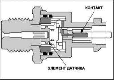 |
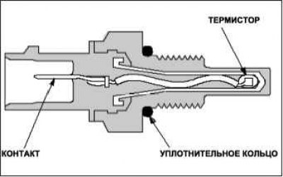
Fuel temperature sensor
The fuel temperature sensor is installed in the fuel filter. The fuel temperature sensor is a resistor that changes its resistance depending on temperature (thermistor). The resistance of the thermistor decreases as the temperature of the fuel rises.
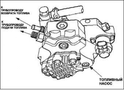
Fuel pump
The fuel pump takes the right amount of fuel, which then enters the common injection pipeline under high pressure.
Fuel Injection Main Relay PGM-FI
PGM-FI main fuel injection relay energizes every time the ignition is turned on (II), supply voltage to the ECM battery.
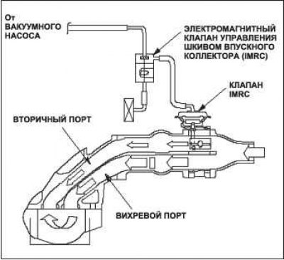
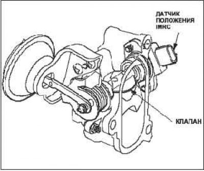
Intake manifold pulley control (IMRC)
The IMRC valve ensures combustion stability at low speeds by opening and closing. The IMRC valve opens and closes to create a flow pause between the swirl channel and the secondary port, controlling the amount of swirl flow.
Intake manifold pulley control position sensor (IMRC)
The IMRC position sensor detects the angle of the IMRC valve.
Reinforcement of the turbocharger
This model is equipped with a turbocharger model with a variable section nozzle. It maintains the optimal balance of backpressure and overpressure for engine speed and load by opening and closing a variable nozzle located at the periphery of the turbine and adjusting the flow rate and pressure of the exhaust gases at the turbocharger inlet.
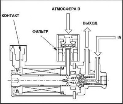
Note. The figure shows the turbocharger boost solenoid valve.