
Contents: Examination ⇊ Removal and installation ⇊
Examination
1. Remove the center console and selector trim (see chapter "Body").
2. Disconnect the connector shown in the figure.
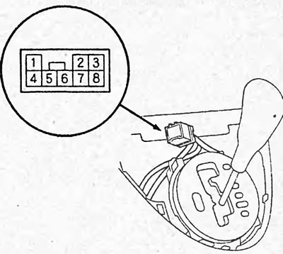
3. Set the selector to position "P" and make sure there is conductivity between terminals "3" and "8". Move the selector from position "P" and make sure there is no conductivity between these terminals.
Removal and installation
1. Remove the center console and selector trim (see chapter "Body").
2. Remove the selector position indicator panel (see section "Selector").
3. Disconnect and remove the selector lock solenoid valve connector.
4. Remove the selector lever "S" position sensor/selector lever lock solenoid valve/selector lever "P" position sensor connector from the selector lever bracket.
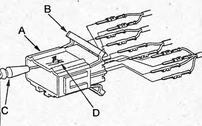
5. Remove the cover (B) of the connector (A) of the selector lever "S" position sensor and the selector lever lock solenoid valve. Using a screwdriver (C), remove the contacts (D) from the connector.
6. Remove the sensor (B) and bracket (A) of the selector lever "P" position sensor.
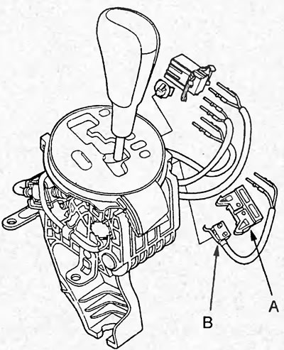
7. Replace the sensor with a new one.
8. Connect the contacts to the connector, referring to the figure and table below.
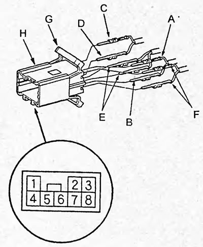
A - white and black wire, B - black wire, C - red wire, D - blue wire, E - red and black wire, F - green wire, G - connector cover, H - connector.
| output No | Wire color |
| 1 | Red |
| 2 | White and black |
| 3 | Green |
| 4 | Blue |
| 5 | Red and black |
| 6 | Red and black |
| 7 | Black |
| 8 | Green |
9. Close the cover (G) of the connector (H).
10. Install the sensor (A) and the bracket (C) of the "P" position sensor to the selector (B).
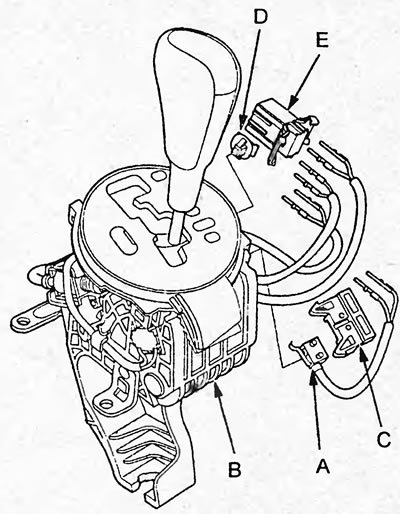
11. Install the retainer (D) onto the connector (E). Install the connector onto the selector and connect it.
12. Install and connect the selector lock solenoid valve connector.
13. Install the selector position indicator panel.
14. Install the center console and selector trim (see chapter "Body").