
Contents: Removal ⇊ Installation ⇊
Removal
1. Remove the lower center trim of the instrument cluster (see chapter "Body").
2. Remove the selector trim (see chapter "Body").
3. Move the selector to the "R" position.
4. Slide the adjustment cap (B) of the cable end (A) as shown in the figure. Using pliers (D), remove the cable retainer (C).
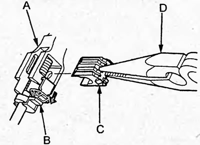
5. Move the selector to the "N" position and remove the cable from the cable end.
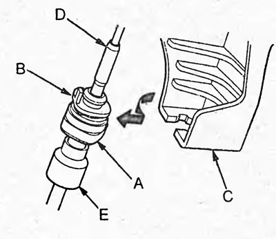
6. Turn the protruding part (B) of the holder (A) 90° as shown in the figure and remove the cable from the bracket (C).
Note: When removing the cable, do not remove the guide bushing (D) and damper (E).
7. Remove the bracket (D).
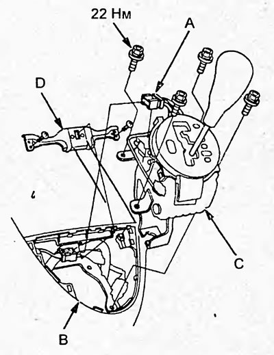
8. Disconnect the connector (A) of the selector lever "S" position sensor and the selector lever lock solenoid valve.
9. Apply protective tape to the lower center instrument cluster trim (B) to prevent damage.
10. Loosen the bolts and remove the selector (C).
11. Remove the selector lever position sensor "S" from the selector bracket.
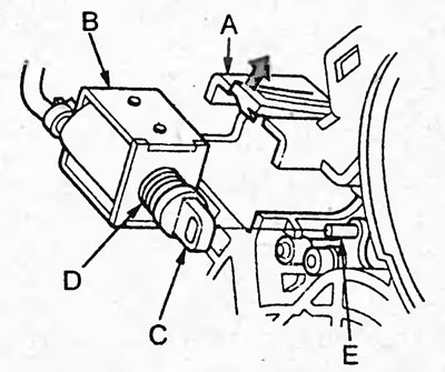
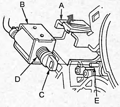
12. Bend the retainer (A) as shown in the figure and remove the selector lock solenoid valve (B). Hold the plunger (C) and spring (D) during removal.
Installation
1. Install the solenoid valve on the bracket and make sure the retainer holds the solenoid valve securely. When installing, align the hole in the plunger (C) with the pin (E).
2. Install the selector lever position sensor "S" onto the selector bracket.
3. Apply protective tape to the lower center trim of the instrument cluster to prevent damage. Install the selector and tighten the bolts.
4. Connect the connector of the selector "S" position sensor and the selector lock solenoid valve.
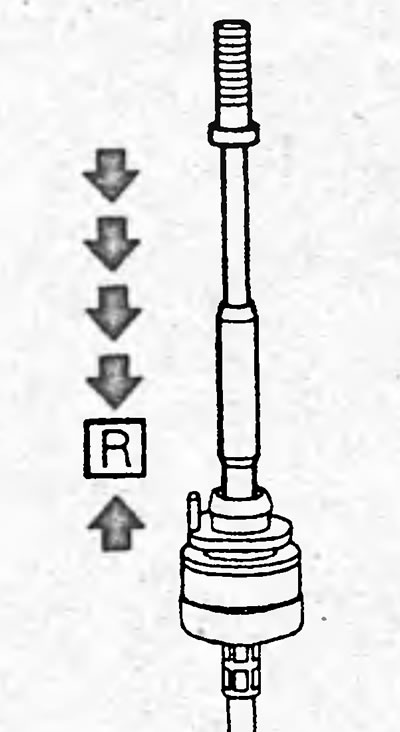
5. Turn on the ignition and make sure that the selector position indicator "R" is lit.
6. If the "R" indicator does not light, set the cable to the "R" position, referring to the figure.
7. Turn off the ignition.
8. Set the selector to the "N" position.
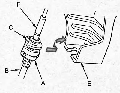
9. Install the cable into the bracket (E) and turn the protruding part (C) of the cable holder (A) (B) 90° as shown in the figure.
Note: Make sure the guide bushing (F) is installed correctly.
10. Make sure the cable is installed securely.
11. Move the selector to the "R" position.
12. Install the end of the cable (A) into the end (B) of the cable
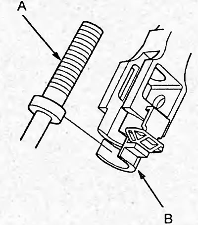
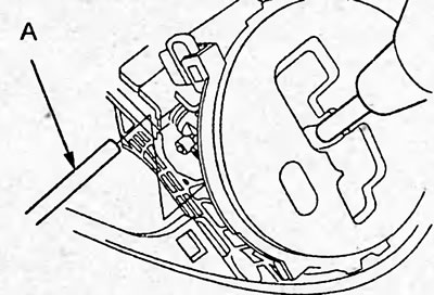
13. Install the pin (A) with a diameter of 6 mm into the hole of the selector as shown in the figure to fix the position of the selector.
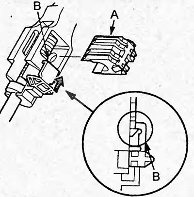
14. Install the new retainer (A) and slide the adjustment cover (B) as shown in the figure.
15. Remove the pin installed to fix the selector position.
16. Move the selector to each position and check that the indicator readings correspond to the selector position.
17. Start the engine and, by moving the selector to each position, make sure that the gearbox control cable is adjusted correctly.
18. Install the selector trim (see chapter "Body").
19. Install the lower center instrument cluster trim (see chapter "Body").