
Contents: Examination ⇊ Installation ⇊
1. Remove the gearbox (see chapter "Manual transmission").
2. Remove the clutch release fork boot (A) from the clutch housing (B).
3. Remove the clutch release fork (C) by squeezing the spring (D) with pliers.
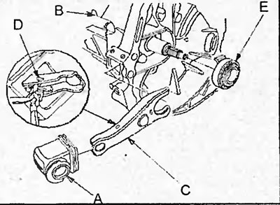
4. Remove the release bearing (E).
5. Install the special device to secure the flywheel.
6. Install a special device for centering the disks.
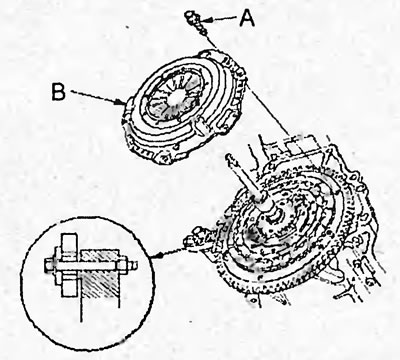
7. Loosen the bolts (A) one turn at a time to ensure that the spring is completely released from pre-compression.
8. Loosen the mounting bolts (A) and remove the clutch housing (B) with the driven clutch disc.
9. Remove the driven clutch disc and the special tool for centering the discs.
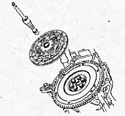
10. In several passes, unscrew the flywheel mounting bolts and remove the flywheel.
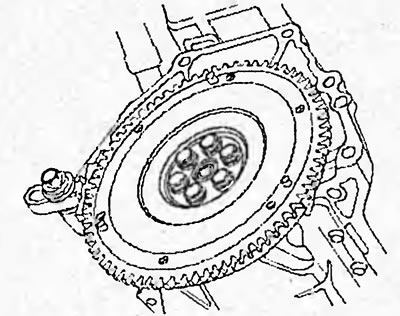
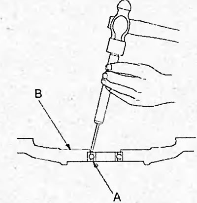
11. Remove the transmission input shaft support bearing (A) from the flywheel (B).
Caution: Do not remove the bearing unless replacing it.
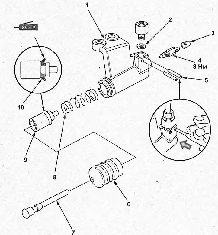
Clutch release drive slave cylinder. 1 - clutch slave cylinder housing, 2 - ring seal, 3 - bleeder cap, 4 - bleeder nipple, 5 - pin, 6 - dust cover, 7 - rod, 8 - spring, 9 - piston, 10 - sealing cuff.
Examination
1. Check the clutch housing.
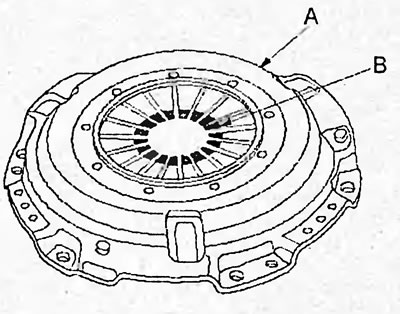
a) Check the clutch housing (A) and diaphragm spring petals (B) for damage, bending or excessive wear.
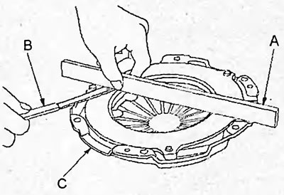
b) Using a ruler (A) and feeler gauge (B), measure the clearance between the pressure plate (C) and the ruler as shown in the figure.
- Nominal clearance - 0.03 mm
- Maximum gap - 0.15 mm
c) Install the dial indicator (A) on the cylinder block.
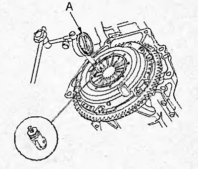
d) Rotate the flywheel to measure the deflection of the tops of the diaphragm spring petals.
- Nominal deviation from plane - 0.6 mm
- Maximum deviation from plane - 0.8 mm
If one of the measured values does not correspond to the established standard, replace the clutch housing.
2. Check the clutch driven disc.
a) Check the clutch slave disc for damage, oil stains and signs of overheating,
b) Using a caliper, measure the thickness of the clutch driven disc.
Nominal thickness:
models produced before 10/2001 — 8.3-9.0 mm
models produced since 10/2001:
- models with D17A engine - 8.5-9.1 mm
- models with D15B engine - 8.3-9.0 mm
Minimum allowable thickness:
models produced before 10/2001 - 5.7 mm
models produced since 10/2001:
- models with D17A engine - 5.8 mm
- models with D15B engine - 5.7 mm
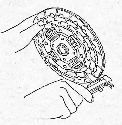
c) Check the thickness of the linings on both sides of the disc in relation to the rivet heads. If the lining thickness is less than the minimum, replace the disc.
Minimum overlay thickness:
- models with D15A engine - 0.2 mm
- models with D17A engine - 0.8 mm
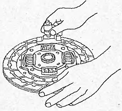
Replace the clutch disc if necessary.
3. Check the flywheel.
a) Make sure that the flywheel ring gear is not damaged.
b) Check the flywheel surface adjacent to the driven clutch disc for uneven wear, deep grooves and scoring.
c) Using a dial indicator (B), check the axial runout of the flywheel (A). If the axial runout exceeds the established norms, replace the flywheel.
- Nominal runout - 0.06 mm
- Maximum permissible runout is 0.15 mm
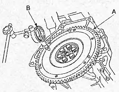
Replace the flywheel if necessary.
4. Apply axial pressure to the release bearing and rotate it. If the bearing is seized or there is significant resistance to rotation, replace the bearing.
Note: Do not flush the release bearing in any liquid. The sealed bearing does not require flushing or lubrication.
Installation
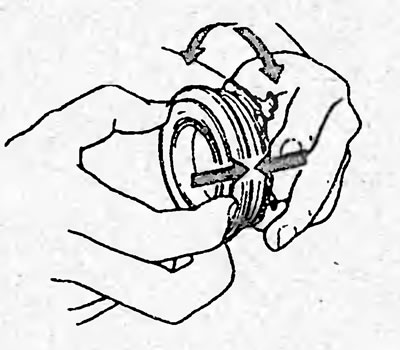
1. Using a drift and hammer, install the new transmission input shaft support bearing into the flywheel.
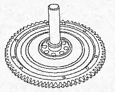
2. Align the holes in the flywheel with the pins on the crankshaft and install the flywheel. Install the washers and tighten the bolts finger tight.
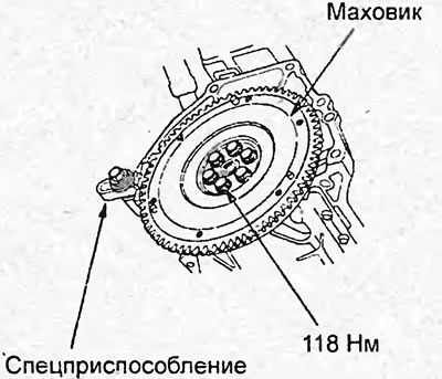
3. Using a special tool, secure the flywheel and tighten the bolts to the specified torque.
Tightening torque - 118 Nm
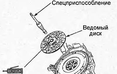
4. Apply grease to the splines of the driven clutch disc. Install the driven clutch disc and use a special tool to center it.
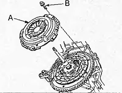
5. Install the clutch cover (A) and tighten the bolts (B) finger tight.
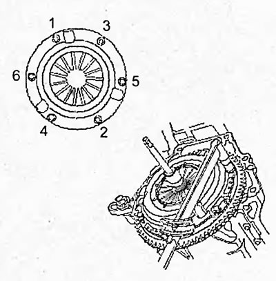
6. Tighten the clutch housing mounting bolts in several passes in the order shown in the figure.
Tightening torque - 25 Nm
7. Remove the special tool for centering the discs.
8. Check the height of the diaphragm spring petals.
9. Apply grease to the clutch release fork (A), fork bolt (B), release bearing (C) and shaft (D).
Note: The areas to be greased are indicated by hatching in the figure.
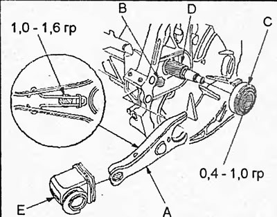
10. Install the release bearing and clutch release fork.
11. Install the clutch release fork boot (E).
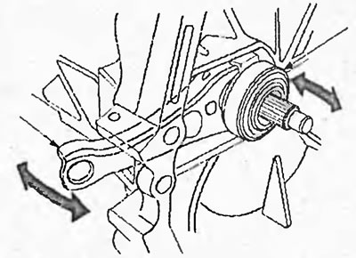
12. By moving the clutch release fork right and left, make sure that the fork is installed correctly and that the bearing moves smoothly.
The text of the article is available on the website HondaBook.ru