
Contents: Checking the rotor ⇊ Stator check ⇊ Checking the brushes ⇊ Checking the brush springs ⇊ Checking the rectifier unit ⇊ Assembly(D15B, D17A) ⇊
Checking the rotor
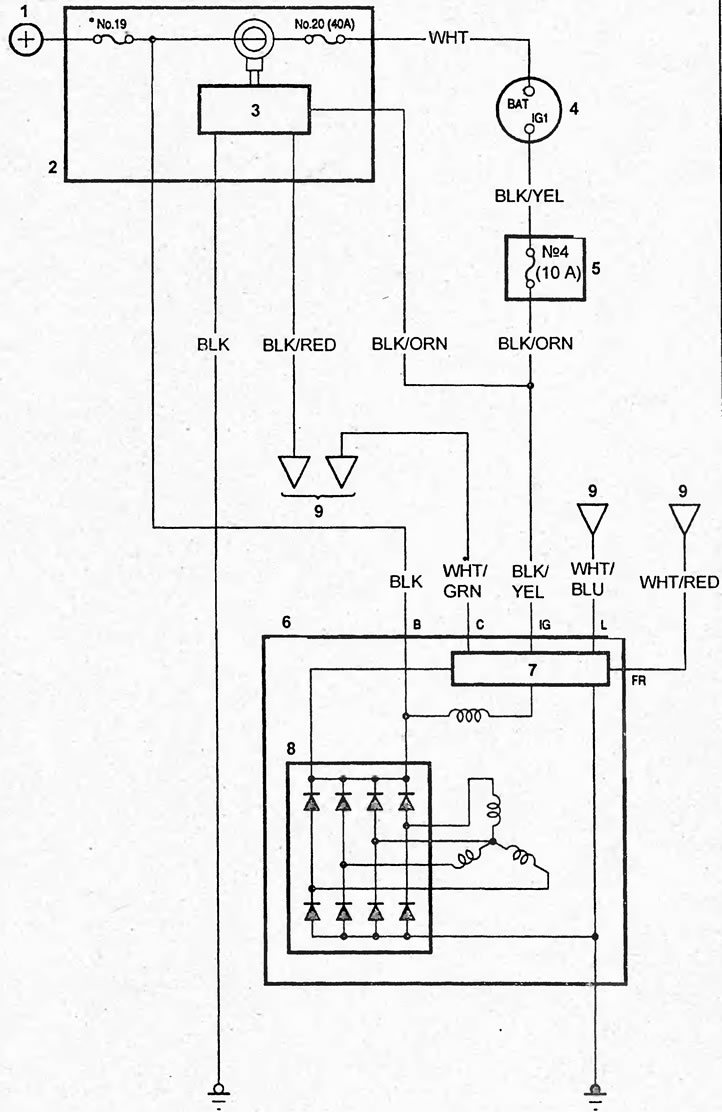
Electrical circuit of the generator.1 - battery, 2 - engine compartment relay and fuse box, 3 - supply voltage control system unit, 4 - ignition switch, 5 - mounting block in the passenger compartment, 6 - generator, 7 - voltage regulator, 8 - rectifier unit, 9 - control unit.
1. Check if there is a break in the excitation winding.
Using an ohmmeter, measure the resistance between the contact rings. Nominal resistance (in the "cold" state):
- D15B, D17A — 1.84-2.1 Ohm
- K20A - 2.2 - 3.0 Ohm
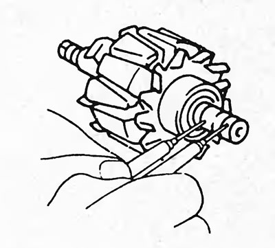
If resistance tends to infinity (the circuit is open), then replace the rotor or generator.
2. Check if the excitation winding is shorted to ground.
Using an ohmmeter, check for continuity between the rotor pole and the slip rings and rotor shaft.
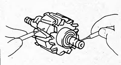
If the resistance is "0" (the circuit is closed), then replace the rotor.
3. Check the slip rings.
a) Check the working surfaces of the contact rings. They should not have any burrs or chips.
b) Using a caliper, measure the diameter of the slip rings.
Nominal diameter:
- D15B, D17A — 22.7 mm
- K20A - 14.4 mm
Minimum diameter:
- D15B, D17A — 21.7 mm
- K20A - 14.0 mm
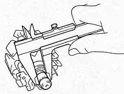
If the diameter of the slip rings is less than the minimum diameter, replace the rotor.
Stator check
1. Check for a break in the starter winding. Use an ohmmeter to measure the resistance between the terminals of the stator winding coils.
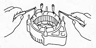
If resistance tends to infinity (the circuit is open), then replace the stator.
2. Check if the stator winding is shorted to ground.
Using an ohmmeter, measure the resistance between the stator housing and the terminals of the stator winding coils.
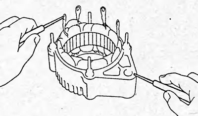
If the resistance is "0" (the circuit is closed), then replace the stator.
Checking the brushes
Measure the length of the protruding part of the brushes.
Nominal length:
- K20A - 10.5 mm
- D15B, D17A — 19.0 mm
Minimum length:
- K20A - 1.5 mm
- D15B, D17A — 5.0 mm
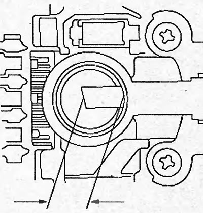
D15B, D17A.
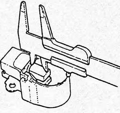
K20A.
If the brush length is less than the minimum length, replace the brushes and brush holder assembly.
Checking the brush springs
Using a spring balance, measure the tension of the brush springs at the moment they break away from the brush.
Nominal force:
- D15B, D17A — 3.3-4.1 N
- K20A — 2.9 - 3.5 N
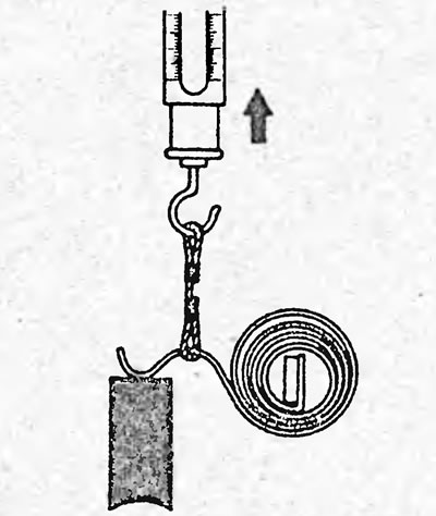
If the spring force is not within the specified range, replace the brush springs.
Checking the rectifier unit
1. Check the conductivity between terminals "B" and "P" and between terminals "E" and "P" of each pair of diodes of the rectifier block.
Conductivity must be present in only one direction as shown in the figure.
If necessary, replace the rectifier unit assembly.

K20A.
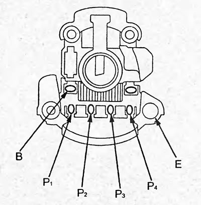
D15B, D17A.
Assembly(D15B, D17A)
1. Install the alternator pulley onto the front cover and tighten the pulley mounting nut.
Tightening torque - 111 Nm
2. Remove any engine oil or grease from the rotor slip rings.
3. Install the voltage regulator.
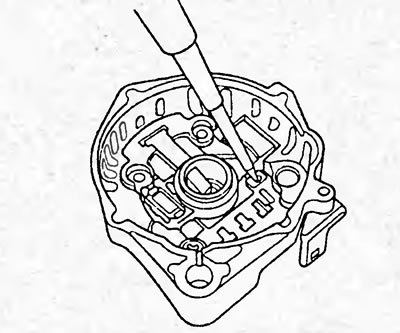
4. Install the stator, fixing the terminals of the winding coils as shown in the figure.
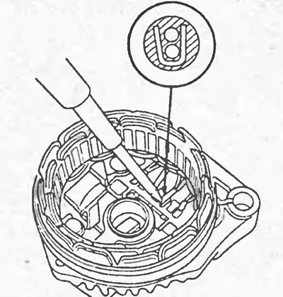
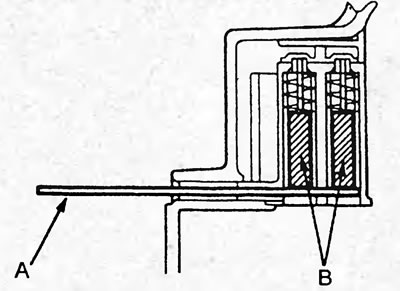
5. Press the brushes (B) into the brush holder and insert the plate (A) with a width of 1.8 mm as shown in the figure, fixing the brushes inside.
6. Heat the surface in the area of the rear bearing with warm air (50 - 60°) for 5 minutes.
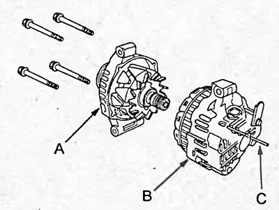
7. Place the front cover (A) complete with rotor on a level surface, install the rear cover (B) on the front cover, tighten the four mounting bolts and insert the rod (C).
8. After assembling the generator, check the smooth rotation of the generator pulley.