
Examination
1. Access to the electrical wiring connector of the sensor-switch is possible from the engine compartment.
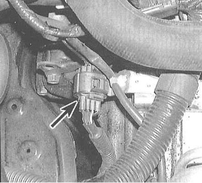
2. Disconnect the 10-track transmission position sensor-switch connector.

3. Check the connector for the compliance of the states of the sensor-switch with the conductivity map. Move the selector lever alternately to each of the positions.
4. At negative results of check make adjustment of the gauge switch. If the switch cannot be adjusted, replace it.
Adjustment
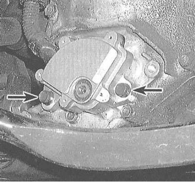
1. Move the selector lever to position "N" and loosen the sensor mounting nuts.
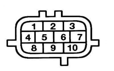
2. Disconnect the 10-pin connector and connect an ohmmeter to terminals 1 and 3.
3. Remove the cover and slightly loosen the sensor-switch mounting bolts. Turn the sensor-switch to the position "N", - a click should be heard, and the ohmmeter will record the appearance of conductivity.
4. Tighten the mounting bolts, replace the cover and connect the connector.
Replacement
1. Jack up the car and put it on stands.

2. Disconnect the 10-pin connector. Turn out a bolt of the holder of a plait of electroconducting.
3. Move the selector lever to position "N".
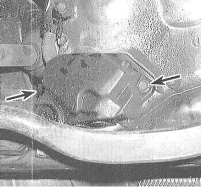
4. Remove the cover of the AT position sensor-switch, then unscrew the sensor-switch mounting bolts.
 |  |
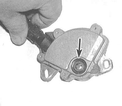
5. Move the new sensor-switch to the position corresponding to the position "N", make sure the selector lever is also in the "N".
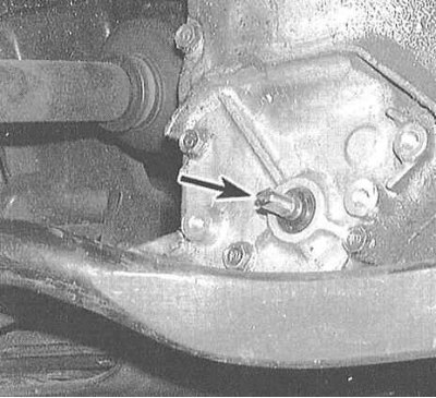
6. Put the sensor-switch on the control axis and, making sure that it remains in position "N", tighten the fixing bolts.
7. Connect the electrical wiring, fix the harness and replace the cover.
8. Make sure the engine only starts in the "N" And "R" selector lever.