Removal/Installation
The location of the SRS parts is given in this section. Review parts locations, safety precautions, and work procedures in the SRS before performing repairs or maintenance.
Note: Before removing the steering column for SRS. remove the airbag and cable reel.
1. Remove the steering wheel.
2. Remove the driver's instrument panel lower cover.
3. Remove the combination switch from the steering column shaft by disconnecting the connectors.
4. Disconnect the ignition switch connectors.
5. Remove the steering cross housing.
6. Remove the steering cross bolts.
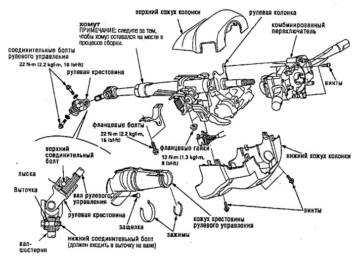
7. Disconnect the steering crosspiece by moving the crosspiece towards the column, and remove it from the column shaft.
8. Remove the steering column by unscrewing the connecting nuts and bolt.
9. Installation is the reverse of removal.
Note:
- Make sure that the steering cross is assembled as follows:
A. Insert the upper end of the steering cross into the steering shaft (align the bolt hole with the flat on the shaft), and loosely install the upper connecting bolt.
b. Slide the lower end of the steering cross onto the drive shaft (align the bolt hole with the groove on the shaft), and loosely install the lower connecting bolt. Make sure the lower connecting bolt is securely seated in the groove on the pinion drive shaft.
V. Press down on the steering crosspiece to ensure it is in place. Then tighten the bolts.
- Make sure that the wires are not snagged or caught in any part while installing the column.
- Make sure the wire connections are directed and made correctly. Make sure the connectors are connected.
Inspection
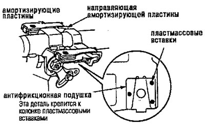
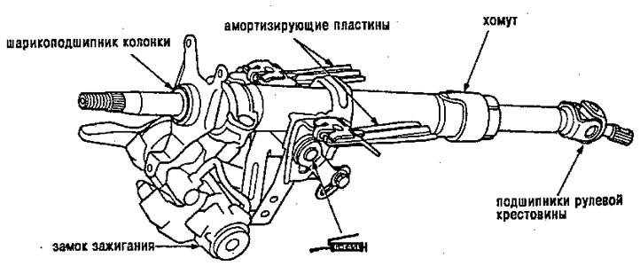
Note: the steering wheel can be of two types (Type A and Type A steering column are shown in the figure; type B is identical, except for the arrangement of shock-absorbing plates.
- Check the steering column ball bearing and steering cross bearings for play and smooth rotation. If there is noise or excessive play, replace the spider or column assembly.
- Check the clamp for damage. If it is damaged, replace it.
- Check the shock plates, shock plate guides and anti-friction pads for bending or damage. Replace them as a unit if they are warped or broken.
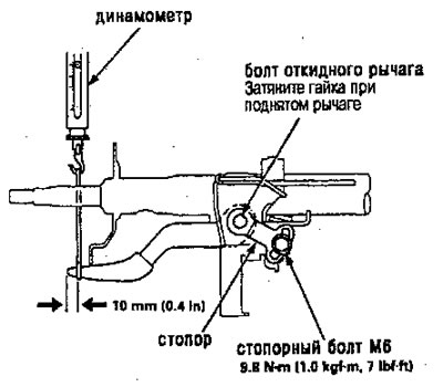
1. Move the folding lever from the weakened position to the clamped position for 3 to 5 minutes; then measure the tilt arm pretension at a distance of 10mm from the end of the tilt arm.
Pre-tension: 70 - 90 N (7-9 kgf)
2. If the readings are not within specifications, adjust the preload using the following procedures.
A. Loosen the tilt lever and place the steering column in neutral position,
b. Unscrew the locking bolt MB and remove the stopper.
V. Adjust the tension by turning the tilt arm bolt from left to right
d. Pull the tilt lever to the upper position and install the stopper. Check the tension of the tilt arm. If the readings are still out of specification, repeat the procedures from (A) before (G) .
Attention. Be careful not to loosen the tilt arm while installing the stopper or tightening the MB stopper bolt.