
Removal
Note: Wash off dirt and oil from the valve body, lines and gearbox using solvent and a brush. Dry with compressed air.
1. Drain the power steering fluid.
2. Raise the front of the car and secure it to the safety stands in appropriate places,
3. Remove the front wheels.
4. Vehicles with SRS: Before disconnecting the steering crosspiece, remove the steering wheel.
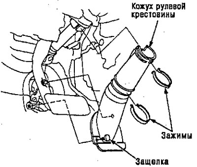
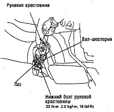
5. Remove the steering unit cover.
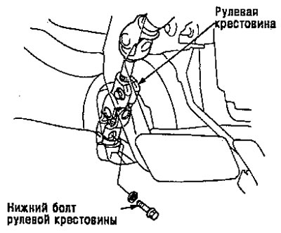
6. Remove the lower bolt of the steering crosspiece, and disconnect the steering crosspiece by moving it towards the column.
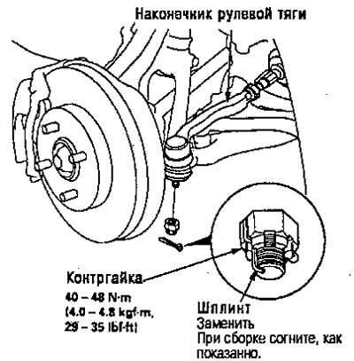
7. Pull the cotter pin out of the lock nut and remove the nut.
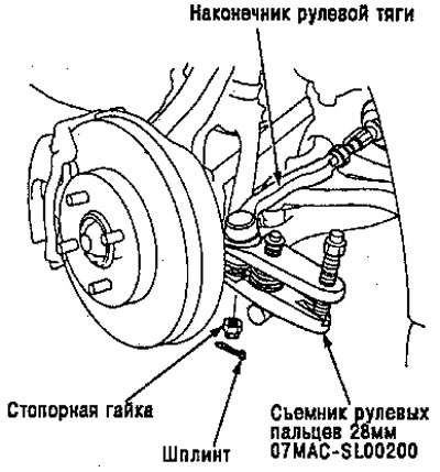
8. Install a 10mm hex nut onto the ball joint. Make sure that the 10mm hex nut matches the end of the steering pin, otherwise the threaded part of the steering pin may be damaged by the special tool.
Note: Remove the steering joint using a 28mm puller (07MAS SL00200).
9. Disconnect the steering rod and joint using a special tool.
Attention. Avoid damaging the steering joint boot.
10. Remove the left tie rod end (for right-hand drive vehicles - right), then turn the steering rack to the right (for right-hand drive vehicles turn left).
11. Disconnect exhaust pipe A or TWC.
12. Disconnect the transmission shift rod.
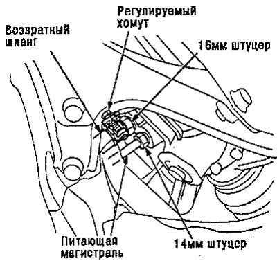
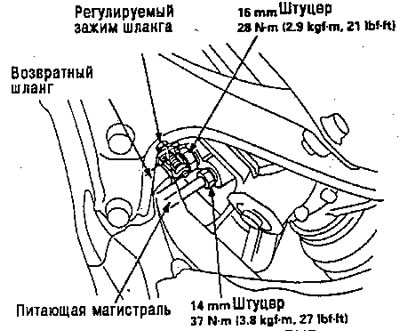
13. Loosen the 14 mm fitting and disconnect the supply line.
14. Loosen the adjustable clamp and disconnect the return hose.
15. Loosen the 16 mm fitting and remove the return hose from the valve body.
Attention. After disconnecting the hose and line, cover the hose and line openings with duct tape or substitute to prevent foreign material from entering the valve assembly body.
Note: Do not loosen lines A and B between the valve body and the cylinder.
Note: LHO shown, RHD symmetrical.
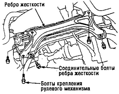
16. Remove the stiffener.
Note: Some rib connecting bolts are used as steering gear mounting bolts. When these bolts are removed, the steering gear will tilt to the side.
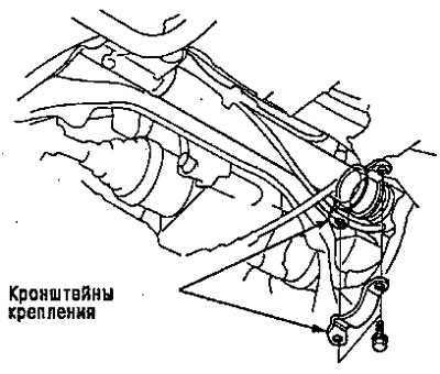
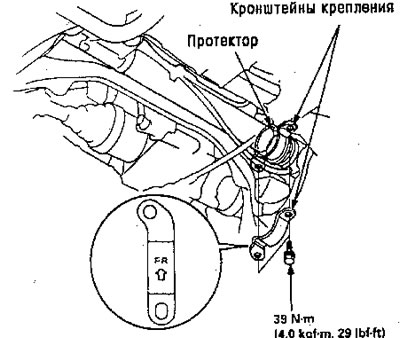
17. Remove the mounting brackets.
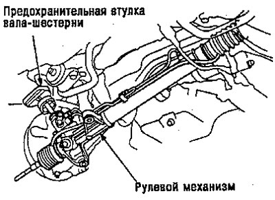
18. Pull the rack and pinion mechanism down to release the pinion drive shaft from the bulkhead and remove the pinion shaft safety sleeve.
19. Slide the rack and pinion to the right to release the left end of the steering rack and tilt the left side down to remove it from the vehicle.
Caution: Be careful not to bend or damage the supply line and cylinder line when removing the steering gear.
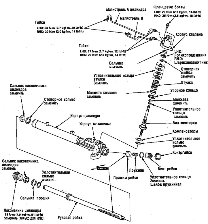
Steering rack parts
Note:
- Wash the disassembled parts in the solution and dry them with compressed air. Do not immerse rubber seals in the solution.
- Always replace O-rings and rubber seals with new ones before assembly.
- Apply power steering fluid or lubricant () to the parts indicated in the assembly diagram.
- Do not allow dust or other foreign materials to enter the power steering system.
- Use appropriate special tools» where necessary.
Installation
Attention. Be careful not to bend or damage the supply line and cylinder lines when installing the mechanism.
1. Before installing the mechanism, move the steering rack to the right (for RHD: left).
2. Install the mounting protector on the steering mechanism.
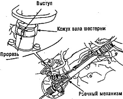
3. Install the gear shaft housing, and install the gear shaft through the bulkhead.
Note: Align the slot on the gear drive shaft with the tab on the valve body.
4. Install the mounting brackets with two bolts securing the mechanism to the tread.
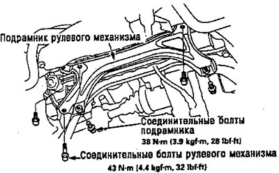
5. Secure the steering gear subframe with two mechanism mounting bolts and connecting bolts.
Attention. Make sure the air line is not caught or pinched by the steering subframe.
Note: Install the bolts loosely at first, then tighten them firmly for security.
6. Install the return hose joint by tightening the 16 mm union nut.
7. Securely attach the return hose and tighten the bolt clamp from the engine compartment
8. Connect the supply line and tighten the 14 mm union nut.
Note: Make sure the fluid lines, rear crossbar and other parts are not intertwined.
Note: LHD type shown, RHD type is symmetrical.
9. Center the steering rack while it is moving.
10. Before connecting the steering cross, do the following.
For SRS:
Center the cable reel by first rotating it clockwise (approximately two turns) until the arrow reaches the position "directly".
Without SRS (regular steering wheel)
Place the steering wheel in a strictly straight position, turning the wheel from lock to lock.
11. Slide the lower end of the steering cross onto the gear shaft (aligning the hole for the bolt and the groove of the shaft on the same line), and tighten the bottom bolt.
Note:
- Connect the steering shaft and pinion shaft with the rack and SRS cable reel centered.
- Make sure that the lower bolt of the steering gear is seated in the groove on the pinion shaft.
- If the steering wheel and rack are not centered after assembly, reconnect the lower end of the crosspiece.
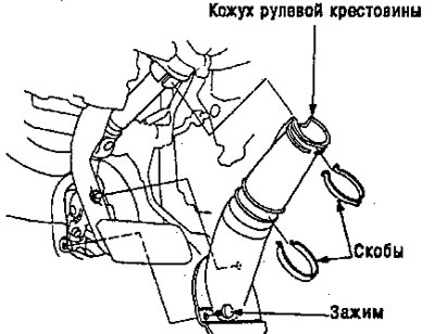
12. Secure the steering cross housing with a clamp and staples.
13. Cars with SRS: install the steering wheel and airbag.
14. Attach the tie rod ends to the steering knuckles, tighten the lock nut to the specified torque and install new cotter pins.
Note: Before attaching the tie rod ends, check the threaded part of the tie rod for contamination with grease, remove it if necessary.
Attention. Tighten the locknut to less than the required torque, then tighten it until the groove aligns with the pin hole. Do not achieve alignment along one line by loosening the nut.
15. Install exhaust pipe or TWC.
16. Connect the gear shift rod.
17. Install the wheels straight.
18. Fill the system with power steering fluid and bleed air from the system.
19. After installation, perform the following checks.
- Start the engine, let it idle, and turn the steering wheel from lock to lock for a while to warm up the fluid.
- Check the steering gear housing for leaks.
- Adjusts the front finger.
- Check the steering wheel spoke angle. Adjust by turning the right and left tie rods as necessary.
Note: Turn the right and left tie rods equally.
Replacing the ball joint boot
1. Remove the boot retaining ring and boot.
Attention: do not contaminate the installation area of the boot with grease.
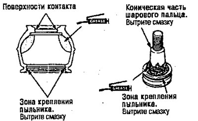
2. Apply lubricant to the inner surface and edges of the boot.
3. Wipe off the grease from the sliding surface of the ball pin, then apply fresh grease to the bottom.
Attention:
- Maintains lubricant at the boot installation site and the conical surface of the ball pin.
- Protect the inner surface of the boot from dust, dirt and other foreign objects.
4. Place the boot carefully into the boot groove, then squeeze the air out of the boot.
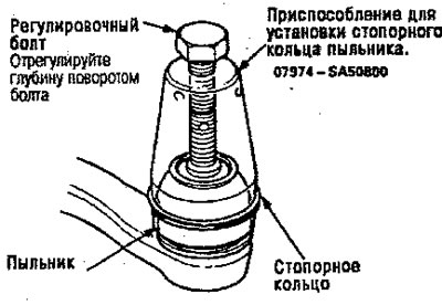
5. Install a special tool with a pressure bolt at the end of the tool, aligned with the groove on the boot. Slide the retaining ring from the tool to the installation location.
Attention: after installing the boot, check the conical surface for contamination with grease and wipe it off if necessary.