
Contents: Removal ⇊ Installation ⇊
To replace the grease in the joint, or to replace the joint itself, you must remove the axle shaft. On cars produced since 1998, the axle shaft is non-separable and if the CV joint fails, the axle shaft must be replaced. It should be noted that the axle shaft components on vehicles with ABS brake systems are slightly different. The procedure for removing and installing the axle shaft is the same for cars with automatic and manual transmissions.
Removal
1. Disconnect the battery from ground.
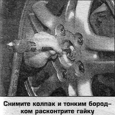
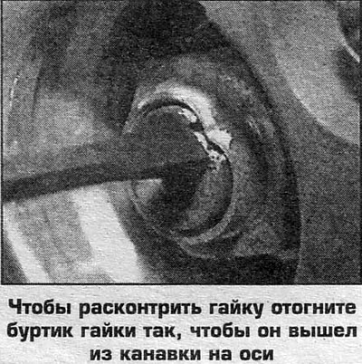
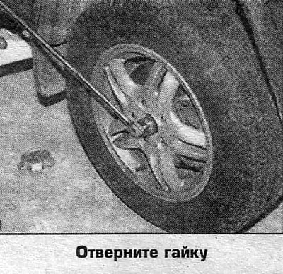
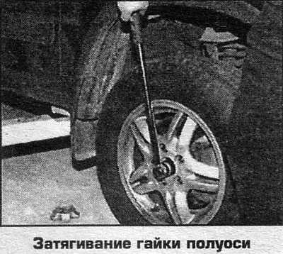
2. Unlock and unscrew the axle shaft nut (photo).
3. Raise the vehicle, unscrew the axle nut and remove the wheel.
4. Drain the oil from the differential housing. There is no need to drain the oil if you are removing only the left axle shaft on CR-V and 4-cylinder Odyssey vehicles, or the right axle shaft on 6-cylinder Odyssey vehicles.
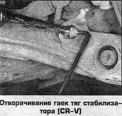
5. Disconnect the stabilizer rods from the strut (or from the suspension arm).
6. On CR-V and 4-cylinder Odysseys, remove the pinch bolt and through bolt and remove the yoke from the strut.
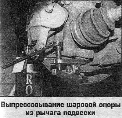
7. Remove the cotter pin and unscrew the ball joint nut, press the ball joint out of the suspension arm.
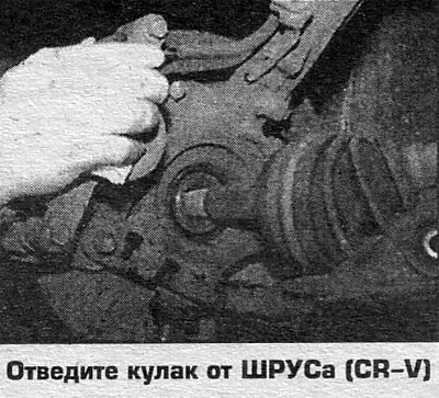
8. Remove the ball joint from the steering knuckle by pushing the lever down.
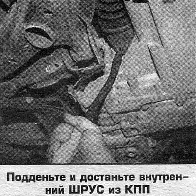
9. Remove the inner CV joint from the gearbox housing by prying it up with a crowbar so that the spring retaining ring in the differential pinion or in the axle shaft is compressed and pressed into the groove.
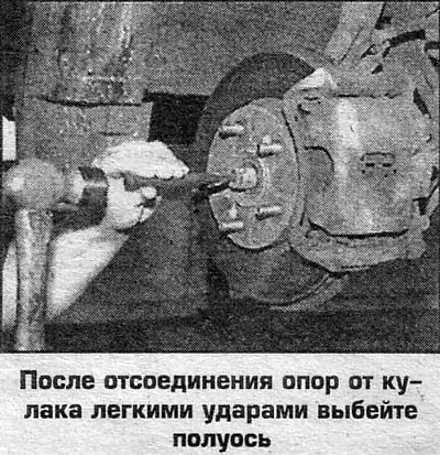
10. Separate the inner CV joint from the intermediate shaft with light blows of a plastic hammer.
11. Remove the axle shaft from the differential (or from the intermediate shaft).
Installation
12. Install the new snap ring into the groove on the splined portion of the axle shaft.
13. If the axle shaft is inserted into the gearbox, lubricate the edges of the seal and the sealing part of the axle shaft with low-viscosity oil.
14. If the axle section is installed on the intermediate shaft, lubricate with high-melting grease, then wipe off the grease in the groove under the spring ring and from part of the splines (every 2-3 splines), to ensure air access.
15. Install the CV joints until they click into place (this ensures that the spring rings are seated correctly).
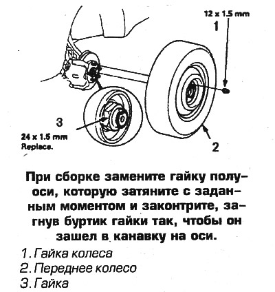
16. Then assembly is carried out in reverse order. Tighten all disassembled suspension fasteners to the torques specified in the technical data (see Ch. 8). On 6-cylinder Odysseys, replace the ball joint key. Replace the axle shaft nut and tighten it to 245 Nm.
 |
 |
 |
 |
 |
 |
 |
 |
 |
 |