


Repair of gasoline engine of car Honda CR-V 2
.
Engine assembly (engine removal)
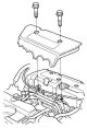
Note: To avoid damaging the paintwork, cover the fenders with cloth. To avoid damaging the wiring, disconnect it carefully by grasping the connector. To avoid incorrect connections, label all electrical wiring and...
Note: To avoid damaging the paintwork, cover the fenders with cloth. To avoid damaging the wiring, disconnect it carefully by grasping the connector. To avoid incorrect connections, label all electrical wiring and...
Engine assembly (engine installation)
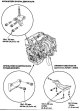
1. Install the accessory brackets and tighten the bolts and nuts to the specified torque. 2. Roll the engine under the car. Attach a chain winch to the engine, then lift the engine until it is in the desired position in...
1. Install the accessory brackets and tighten the bolts and nuts to the specified torque. 2. Roll the engine under the car. Attach a chain winch to the engine, then lift the engine until it is in the desired position in...


Checking engine compression
1. Warm up the engine to normal operating temperature (before turning on the cooling fan). 2. Turn the ignition key to the OFF position. 3. Remove the cover from the intake manifold. 4. Disconnect the connectors from...
1. Warm up the engine to normal operating temperature (before turning on the cooling fan). 2. Turn the ignition key to the OFF position. 3. Remove the cover from the intake manifold. 4. Disconnect the connectors from...

Testing VTEC valve rocker arms
1. Remove the cover from the cylinder head. 2. Set the piston of cylinder No. 1 to TDC. 3. Check that the primary intake rocker arm (A) moves independently of the secondary intake rocker arm (B). If the primary intake...
1. Remove the cover from the cylinder head. 2. Set the piston of cylinder No. 1 to TDC. 3. Check that the primary intake rocker arm (A) moves independently of the secondary intake rocker arm (B). If the primary intake...

Checking the VTC drive
1. Remove the cover from the cylinder head. 2. Remove the automatic tensioner. 3. Loosen the valve rocker arm adjusting screws. 4. Remove the camshaft bracket. 5. Remove the intake camshaft. 6. Make sure that the...
1. Remove the cover from the cylinder head. 2. Remove the automatic tensioner. 3. Loosen the valve rocker arm adjusting screws. 4. Remove the camshaft bracket. 5. Remove the intake camshaft. 6. Make sure that the...

Adjusting valve clearances
Note: Valve adjustment should only be performed when the cylinder head temperature is below 38°C. 1. Remove the cover from the cylinder head. 2. Set the piston of cylinder No. 1 to TDC. The stamped mark (A), marked with...
Note: Valve adjustment should only be performed when the cylinder head temperature is below 38°C. 1. Remove the cover from the cylinder head. 2. Set the piston of cylinder No. 1 to TDC. The stamped mark (A), marked with...

Removal and installation the crankshaft pulley
Removal 1. Remove the front wheels. 2. Remove the mud deflector. 3. Secure the pulley with the handle (A) and holder (B). 4. Remove the bolt using a 19mm socket (C) and a pry bar. Installation 1. Clean the crankshaft...
Removal 1. Remove the front wheels. 2. Remove the mud deflector. 3. Secure the pulley with the handle (A) and holder (B). 4. Remove the bolt using a 19mm socket (C) and a pry bar. Installation 1. Clean the crankshaft...

Removal the timing chain
Note: Do not expose the timing chain to magnetic fields. 1. Turn the crankshaft pulley so that the TDC mark (A) is aligned with the arrow (B). 2. Remove the front wheels. 3. Remove the mud deflector. 4. Remove the drive...
Note: Do not expose the timing chain to magnetic fields. 1. Turn the crankshaft pulley so that the TDC mark (A) is aligned with the arrow (B). 2. Remove the front wheels. 3. Remove the mud deflector. 4. Remove the drive...

Installing the timing chain
Note: Do not expose the timing chain to magnetic fields. 1. Set the crankshaft to TDC and align the TDC mark (A) on the crankshaft sprocket with the arrow (B) on the cylinder block. 2. Set the camshafts to TDC. The...
Note: Do not expose the timing chain to magnetic fields. 1. Set the crankshaft to TDC and align the TDC mark (A) on the crankshaft sprocket with the arrow (B) on the cylinder block. 2. Set the camshafts to TDC. The...

Removal/installing automatic tensioner
Removal 1. Remove the front chain cover. 2. Turn the crankshaft counterclockwise and compress the automatic tensioner. 3. Align the holes on the retainer (A) and the automatic tensioner (B), then insert the pin (C) with...
Removal 1. Remove the front chain cover. 2. Turn the crankshaft counterclockwise and compress the automatic tensioner. 3. Align the holes on the retainer (A) and the automatic tensioner (B), then insert the pin (C) with...

Installing the oil seal in the chain cover
1. Using a special tool, press the new seal into the chain cover without distortion to the required installation depth. 2. Measure the distance between the chain cover surface and the oil seal. Seal installation depth:...
1. Using a special tool, press the new seal into the chain cover without distortion to the required installation depth. 2. Measure the distance between the chain cover surface and the oil seal. Seal installation depth:...

Checking the timing chain
1. Remove the front wheels. 2. Remove the mud deflector. 3. Remove the drive belt. 4. Remove the cover from the cylinder head. 5. Remove the pulley from the crankshaft. 6. Disconnect the connector from the crankshaft...
1. Remove the front wheels. 2. Remove the mud deflector. 3. Remove the drive belt. 4. Remove the cover from the cylinder head. 5. Remove the pulley from the crankshaft. 6. Disconnect the connector from the crankshaft...
Removal the cylinder head cover
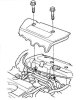
1, Remove the cover from the intake manifold. 2. Remove the four ignition coils. 3. Remove the bolt (A) securing the power steering pump hose bracket. 4. Remove the level indicator (B) and disconnect the breather hose...
1, Remove the cover from the intake manifold. 2. Remove the four ignition coils. 3. Remove the bolt (A) securing the power steering pump hose bracket. 4. Remove the level indicator (B) and disconnect the breather hose...

Removal the cylinder head
Note: To avoid damage to the paintwork, cover the fenders with protective aprons. To avoid damaging the wiring, disconnect it carefully by grasping the connector. To avoid damaging the cylinder head, wait until the...
Note: To avoid damage to the paintwork, cover the fenders with protective aprons. To avoid damaging the wiring, disconnect it carefully by grasping the connector. To avoid damaging the cylinder head, wait until the...

Replacing VTC drive, exhaust camshaft sprocket
Removal 1. Remove the timing chain. 2. While holding the camshaft with a wrench, loosen the electronic timing Control (VTC) drive mounting bolt and the exhaust valve sprocket mounting bolt. 3. Remove the VTC actuator...
Removal 1. Remove the timing chain. 2. While holding the camshaft with a wrench, loosen the electronic timing Control (VTC) drive mounting bolt and the exhaust valve sprocket mounting bolt. 3. Remove the VTC actuator...
Checking the cylinder head for warpage
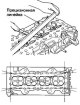
1. Remove the cylinder head. 2. Check the camshaft. 3. Check the cylinder head for warpage. Measure along the edges and in three directions through the center. If the warpage is less than 0.05 mm, regrinding of the...
1. Remove the cylinder head. 2. Check the camshaft. 3. Check the cylinder head for warpage. Measure along the edges and in three directions through the center. If the warpage is less than 0.05 mm, regrinding of the...

Removal the valve rocker arms as an assembly
1. Remove the timing chain. 2. Loosen the valve rocker arm adjusting screws (A). 3. Unscrew the camshaft bracket bolts. To avoid damaging the camshafts, loosen the bolts in a crisscross pattern two turns at a time....
1. Remove the timing chain. 2. Loosen the valve rocker arm adjusting screws (A). 3. Unscrew the camshaft bracket bolts. To avoid damaging the camshafts, loosen the bolts in a crisscross pattern two turns at a time....

Disassembly/assembly of valve rocker arms and axles
Note: To ensure reinstallation in the original position, label components as you remove them. Check the axles and rocker arms. If reused, the valve rocker arms must be installed in their original positions. When...
Note: To ensure reinstallation in the original position, label components as you remove them. Check the axles and rocker arms. If reused, the valve rocker arms must be installed in their original positions. When...

Checking the valve rocker arms and axles
1. Remove the valve rocker arms as an assembly. 2. Measure the axle diameter at the location where the first rocker arm is installed. 3. Set the bore gauge (A) to zero on the axle diameter. 4. Measure the inside...
1. Remove the valve rocker arms as an assembly. 2. Measure the axle diameter at the location where the first rocker arm is installed. 3. Set the bore gauge (A) to zero on the axle diameter. 4. Measure the inside...

Checking the camshaft
Note: Do not turn the camshaft during inspection. 1. Remove the valve rocker arms as an assembly. 2. Place the rocker arm shaft brackets, camshaft and camshaft brackets on the cylinder head and tighten the bolts to the...
Note: Do not turn the camshaft during inspection. 1. Remove the valve rocker arms as an assembly. 2. Place the rocker arm shaft brackets, camshaft and camshaft brackets on the cylinder head and tighten the bolts to the...

Removal valves, springs and seals
Note: Mark the valves and valve springs as you remove them so that you can reinstall all components in their original positions. 1. Remove the cylinder head. 2. Using a socket of suitable diameter (A) and a plastic...
Note: Mark the valves and valve springs as you remove them so that you can reinstall all components in their original positions. 1. Remove the cylinder head. 2. Using a socket of suitable diameter (A) and a plastic...

Checking the valves
1. Remove the valves. 2. Measure the valves in these areas. Inlet valve dimensions: A Standard (new) 34.85-35.15 mm In Standard (new) 108.7-109.5 mm With Standard (new) 5.475-5.485 mm From Limit 5,445 mm Exhaust valve...
1. Remove the valves. 2. Measure the valves in these areas. Inlet valve dimensions: A Standard (new) 34.85-35.15 mm In Standard (new) 108.7-109.5 mm With Standard (new) 5.475-5.485 mm From Limit 5,445 mm Exhaust valve...

Checking the clearance between the valve stem and the valve guide
1. Remove the valves. 2. Extend the valve out of the guide sleeve approximately 10mm, then measure the clearance between the guide sleeve and the stem using a dial indicator by rocking the valve in the guide sleeve. If...
1. Remove the valves. 2. Extend the valve out of the guide sleeve approximately 10mm, then measure the clearance between the guide sleeve and the stem using a dial indicator by rocking the valve in the guide sleeve. If...

Replacing valve guide bushings
1. Check the clearance between the valve stem and the valve guide. 2. As shown in the figure below, a commercially available air pulse punch (A) adjusted to the diameter of the valve guide bushings can be used. In most...
1. Check the clearance between the valve stem and the valve guide. 2. As shown in the figure below, a commercially available air pulse punch (A) adjusted to the diameter of the valve guide bushings can be used. In most...

Restoration of valve seats
1. Check the clearance between the valve stem and the valve guide. If the guides are worn, replace them before machining the valve seats. 2. Restore the valve seats in the cylinder head using a cutter. 3. Carefully file...
1. Check the clearance between the valve stem and the valve guide. If the guides are worn, replace them before machining the valve seats. 2. Restore the valve seats in the cylinder head using a cutter. 3. Carefully file...
Installation of valves, springs and seals
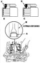
1. Apply engine oil to the valve stems. Insert the valves into the guides. 2. Make sure the valves move freely in the guides. 3. Install the spring seats into the cylinder head. 4. Install new valve seals (A) using the...
1. Apply engine oil to the valve stems. Insert the valves into the guides. 2. Make sure the valves move freely in the guides. 3. Install the spring seats into the cylinder head. 4. Install new valve seals (A) using the...

Installing the valve rocker arms assembly
1. Clean and dry the contact surfaces of bracket No. 5 of the valve rocker arm shaft. 2. Apply the sealant evenly (08X70-K0234M, 08X70 - K0334M or 08X70-X0331S) on the contact surface of the cylinder head under bracket...
1. Clean and dry the contact surfaces of bracket No. 5 of the valve rocker arm shaft. 2. Apply the sealant evenly (08X70-K0234M, 08X70 - K0334M or 08X70-X0331S) on the contact surface of the cylinder head under bracket...

Installing the cylinder head
Installation of the cylinder head is performed in the reverse order of removal. 1. Clean the contact surfaces of the cylinder head and block. 2. Install a new cylinder head gasket (A) and reference pins (B) onto the...
Installation of the cylinder head is performed in the reverse order of removal. 1. Clean the contact surfaces of the cylinder head and block. 2. Install a new cylinder head gasket (A) and reference pins (B) onto the...

Installing the cylinder head cover
1. Thoroughly clean the gasket and the groove under the cylinder head cover. 2. Place the gasket (A) under the cylinder head cover into the groove of the cylinder head cover (B). 3. Make sure contact surfaces are clean...
1. Thoroughly clean the gasket and the groove under the cylinder head cover. 2. Place the gasket (A) under the cylinder head cover into the groove of the cylinder head cover (B). 3. Make sure contact surfaces are clean...


Checking the axial play of the connecting rod and crankshaft
1. Remove the oil pump. 2. Remove the mud deflector. 3. Measure the connecting rod axial play by inserting a feeler gauge between the connecting rod and the crankshaft. Connecting rod axial play: Standard (new)...
1. Remove the oil pump. 2. Remove the mud deflector. 3. Measure the connecting rod axial play by inserting a feeler gauge between the connecting rod and the crankshaft. Connecting rod axial play: Standard (new)...

Replacing the crankshaft main bearings
Checking main bearing clearances 1. Check the oil clearance between the main bearing and the journal by removing the lower block and liners. 2. Clean the main journals and bearings with a clean cloth. 3. Place a piece...
Checking main bearing clearances 1. Check the oil clearance between the main bearing and the journal by removing the lower block and liners. 2. Clean the main journals and bearings with a clean cloth. 3. Place a piece...
Selection of main bearings
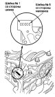
Location of crankshaft markings on the cylinder block 1. On the end surface of the cylinder block there are numbers, letters or dashes stamped which indicate the diameter of the 5 main journals. Write down the...
Location of crankshaft markings on the cylinder block 1. On the end surface of the cylinder block there are numbers, letters or dashes stamped which indicate the diameter of the 5 main journals. Write down the...

Replacing connecting rod bearings
Checking the clearances of connecting rod bearings 1. Remove the oil pump. 2. Remove the mud deflector. 3. Remove the connecting rod cap and bearing shell. 4. Wipe the crankshaft journal and bearing shell with a clean...
Checking the clearances of connecting rod bearings 1. Remove the oil pump. 2. Remove the mud deflector. 3. Remove the connecting rod cap and bearing shell. 4. Wipe the crankshaft journal and bearing shell with a clean...

Removal the oil pan
1. If the engine is still on the vehicle, remove the subframe. a. Drain the engine oil. b. Secure the winch chain to the engine. c. Disconnect the ball joints of the lower suspension arms. g. Unscrew the rear support...
1. If the engine is still on the vehicle, remove the subframe. a. Drain the engine oil. b. Secure the winch chain to the engine. c. Disconnect the ball joints of the lower suspension arms. g. Unscrew the rear support...

Removal the crankshaft and pistons
1. Remove the engine assembly. 2. Remove the gearbox. 3. Remove the oil pan. 4. Remove the oil pump. 5. Remove the cylinder head. 6. Remove the mud deflectors. 7. Remove the 8mm bolts. 8. Unscrew the bearing cap bolts....
1. Remove the engine assembly. 2. Remove the gearbox. 3. Remove the oil pan. 4. Remove the oil pump. 5. Remove the cylinder head. 6. Remove the mud deflectors. 7. Remove the 8mm bolts. 8. Unscrew the bearing cap bolts....
Checking the crankshaft
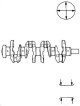
Ovality and taper 1. Remove the crankshaft from the cylinder block. 2. Clean the oil passages on the crankshaft using pipe cleaner and a suitable brush. 3. Clean the keyway and threads. 4. Measure the out-of-roundness...
Ovality and taper 1. Remove the crankshaft from the cylinder block. 2. Clean the oil passages on the crankshaft using pipe cleaner and a suitable brush. 3. Clean the keyway and threads. 4. Measure the out-of-roundness...
Checking the cylinder block and pistons
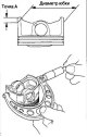
1. Remove the crankshaft and pistons. 2. Check the pistons for deformation or cracks. 3. Measure the piston diameter at point A from the bottom of the skirt. Pistons are available in two standard sizes (without a letter...
1. Remove the crankshaft and pistons. 2. Check the pistons for deformation or cracks. 3. Measure the piston diameter at point A from the bottom of the skirt. Pistons are available in two standard sizes (without a letter...

Clearance between piston and cylinder wall
Clearance between piston and cylinder wall Standard (new) 0.020-0.040 mm Limit 0.05 mm
Clearance between piston and cylinder wall Standard (new) 0.020-0.040 mm Limit 0.05 mm

Cylinder wall honing
Only those cylinders that have burrs or scratches on their walls require honing. 1. Measure the cylinder diameter as described above. If the block is to be reused, hone the cylinder walls and remeasure the cylinder...
Only those cylinders that have burrs or scratches on their walls require honing. 1. Measure the cylinder diameter as described above. If the block is to be reused, hone the cylinder walls and remeasure the cylinder...
Replacement of pistons, piston pins and connecting rods
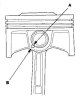
Disassembly 1. Remove the piston from the cylinder block. 2. Apply engine oil to the piston pin retaining rings (A) and rotate them in the grooves until the gaps in the lock align with the slots in the piston pin bore...
Disassembly 1. Remove the piston from the cylinder block. 2. Apply engine oil to the piston pin retaining rings (A) and rotate them in the grooves until the gaps in the lock align with the slots in the piston pin bore...

Replacing piston rings
1. Remove the piston from the cylinder block. 2. Remove the old piston rings (B) using a piston ring expander (B). 3. Thoroughly clean all ring grooves with a broken piston ring or a piston ring groove cleaner with a...
1. Remove the piston from the cylinder block. 2. Remove the old piston rings (B) using a piston ring expander (B). 3. Thoroughly clean all ring grooves with a broken piston ring or a piston ring groove cleaner with a...

Installing pistons
If the crankshaft is already installed 1. Set the crankshaft to the HMT position for each cylinder. 2. Remove the caps from the connecting rods, then install the piston ring installer and make sure the bearing is...
If the crankshaft is already installed 1. Set the crankshaft to the HMT position for each cylinder. 2. Remove the caps from the connecting rods, then install the piston ring installer and make sure the bearing is...
Checking the connecting rod bolts
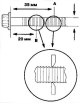
1. Measure the diameter of the connecting rod bolts at points A and B. 2. Calculate the difference in diameter between points A and B, Point A - Point B = Difference in diameter Difference in diameter; Standard: 0-0.1mm...
1. Measure the diameter of the connecting rod bolts at points A and B. 2. Calculate the difference in diameter between points A and B, Point A - Point B = Difference in diameter Difference in diameter; Standard: 0-0.1mm...
Installing the crankshaft
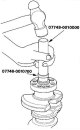
Note: For manual transmission, install the end sleeve when replacing the crankshaft. 1. Press the crankshaft end sleeve using the special tool until the bottom of the special tool rests against the crankshaft. 2. Check...
Note: For manual transmission, install the end sleeve when replacing the crankshaft. 1. Press the crankshaft end sleeve using the special tool until the bottom of the special tool rests against the crankshaft. 2. Check...

Installing the oil pan
1. Remove old sealant from oil pan mating surfaces, bolts and bolt holes. 2. Clean and dry the contact surfaces of the oil pan. 3. Apply sealant, 08C70-K0234M, 08C70-K0334M or 08C70-X0331S, evenly to the contact surface...
1. Remove old sealant from oil pan mating surfaces, bolts and bolt holes. 2. Clean and dry the contact surfaces of the oil pan. 3. Apply sealant, 08C70-K0234M, 08C70-K0334M or 08C70-X0331S, evenly to the contact surface...
This section is available on: russian, bulgarian, belarusian, ukrainian, serbian, croatian, romanian, polish, slovak, hungarian
Link in different formats to this section
TEXTHTMLBB Code
- General information
- User manual
- Technical data
- Maintenance
- Power unit
- Engine repair
- Lubrication system
- Cooling system
- Exhaust system
- Fuel system
- Engine management
- Engine electrical equipment
- Transmission
- Clutch
- Manual gearbox
- Automatic gearbox
- Rear differential
- Drive shafts
- Chassis and running gear
- Steering
- Front suspension
- Rear suspension
- Brake system
- Body and interior
- Exterior (external elements)
- Interior (internal elements)
- Doors, locks and windows
- General information
- Maintenance
- Tips for car owner
- Power unit
- Engine repair
- Engine overhaul
- Cooling and lubrication system
- Engine electrical equipment
- Control system
- Fuel system
- Transmission
- Clutch and drive shafts
- Car gearbox
- Chassis and running gear
- Front suspension
- Rear suspension
- Steering
- Brake system
- Body and interior
- Body service
- Exterior (external elements)
- Interior (internal elements)
- Electrical equipment
- Equipment and devices
- Electrical circuits