
Automatic gearbox of the car Honda CR-V 2
.

Description of the automatic transmission system
General information The automatic transmission combines a 3-piece torque converter and a three-shaft electronically controlled unit that provides 4 forward gears and 1 reverse gear. The gearbox assembly is located in...
General information The automatic transmission combines a 3-piece torque converter and a three-shaft electronically controlled unit that provides 4 forward gears and 1 reverse gear. The gearbox assembly is located in...

Automatic transmission, sectional view
Note: The figure shows the automatic transmission of 4WD models, which is equipped with engines of the K20A4 and K20A5 models; the 2WD models do not have a transfer case on the gearbox; the engine configuration of the...
Note: The figure shows the automatic transmission of 4WD models, which is equipped with engines of the K20A4 and K20A5 models; the 2WD models do not have a transfer case on the gearbox; the engine configuration of the...
Description of the system — couplings
Couplings In a 4-speed automatic transmission, hydraulically driven clutches are used to engage and disengage the automatic transmission gears. When hydraulic pressure is applied to the clutch drum, the clutch piston...
Couplings In a 4-speed automatic transmission, hydraulically driven clutches are used to engage and disengage the automatic transmission gears. When hydraulic pressure is applied to the clutch drum, the clutch piston...

General information — operation of gears
Gears on the drive shaft: The 4th gear pinion is engaged and disengaged from the drive shaft by the 4th gear clutch. The 3rd gear pinion is engaged and disengaged from the drive shaft by the 3rd gear clutch. The reverse...
Gears on the drive shaft: The 4th gear pinion is engaged and disengaged from the drive shaft by the 4th gear clutch. The 3rd gear pinion is engaged and disengaged from the drive shaft by the 3rd gear clutch. The reverse...

Power flow
1st gear Hydraulic pressure is applied to the 1st gear clutch, then the 1st gear clutch engages the 1st gear of the driven shaft with the driven shaft. The intermediate gear of the drive shaft drives the driven shaft...
1st gear Hydraulic pressure is applied to the 1st gear clutch, then the 1st gear clutch engages the 1st gear of the driven shaft with the driven shaft. The intermediate gear of the drive shaft drives the driven shaft...

Electronic control system
Location of components of the electronic control system Note: Left hand drive model shown; the layout on the right-hand drive model is similar.
Location of components of the electronic control system Note: Left hand drive model shown; the layout on the right-hand drive model is similar.

Functional diagram
The electronic control system consists of a powertrain control unit (PCM), sensors and solenoid valves. Electronic control of gear shifting and locking provides convenience in all driving modes. The PCM receives signals...
The electronic control system consists of a powertrain control unit (PCM), sensors and solenoid valves. Electronic control of gear shifting and locking provides convenience in all driving modes. The PCM receives signals...

Gear shift control
Based on signals from various sensors and switches, the PCM instantly determines the selection of a particular gear and actuates the shift solenoid valves A, B, C and E. To control gear shifting in the [D] position when...
Based on signals from various sensors and switches, the PCM instantly determines the selection of a particular gear and actuates the shift solenoid valves A, B, C and E. To control gear shifting in the [D] position when...

GRADE LOGIC CONTROL SYSTEM
Controlled lift When the PCM detects that the vehicle is going uphill in the [D] position, the system increases the 2nd and 3rd gear engagement zone to eliminate the need to frequently shift between 2nd and 3rd gear and...
Controlled lift When the PCM detects that the vehicle is going uphill in the [D] position, the system increases the 2nd and 3rd gear engagement zone to eliminate the need to frequently shift between 2nd and 3rd gear and...

Regulation of pressure in couplings
The RCM unit regulates the pressure in the clutches by activating the solenoid valves A, B and C for regulating the pressure in the automatic transmission clutches. When switching between low and high gears, the clutch...
The RCM unit regulates the pressure in the clutches by activating the solenoid valves A, B and C for regulating the pressure in the automatic transmission clutches. When switching between low and high gears, the clutch...

Blocking management
The shift solenoid valve E regulates the hydraulic pressure by switching the shift lock valve on and off. The PCM unit actuates the gear shift solenoid valve E and the solenoid valve A for regulating the pressure in the...
The shift solenoid valve E regulates the hydraulic pressure by switching the shift lock valve on and off. The PCM unit actuates the gear shift solenoid valve E and the solenoid valve A for regulating the pressure in the...

PCM Electrical Diagram
Electrical diagram of the PCM unit The arrangement of contacts in the PCM connector
Electrical diagram of the PCM unit The arrangement of contacts in the PCM connector

Electrical diagram of the PCM unit (automatic transmission control system)
Electrical diagram of the PCM unit (automatic transmission control system) The arrangement of contacts in the PCM connector
Electrical diagram of the PCM unit (automatic transmission control system) The arrangement of contacts in the PCM connector

PCM Input and Output Signals
The voltage at the PCM contacts and the measurement conditions are given for the connector contacts related to the automatic transmission control system. The voltage at the PCM contacts and the measurement conditions...
The voltage at the PCM contacts and the measurement conditions are given for the connector contacts related to the automatic transmission control system. The voltage at the PCM contacts and the measurement conditions...

Hydraulic drive control
The control valve box contains the main valve body, the control valve body and the servo valve body. The ATF pump is driven by splines on the left end of the torque converter, which is attached to the engine. Fluid...
The control valve box contains the main valve body, the control valve body and the servo valve body. The ATF pump is driven by splines on the left end of the torque converter, which is attached to the engine. Fluid...

Main valve body
The main valve body consists of a manual control valve, gear shift valves A, B, C and E, a pressure reducing valve, a lock-up control valve, a cooler stop valve, a servo valve and ATE pump gears. The purpose of the main...
The main valve body consists of a manual control valve, gear shift valves A, B, C and E, a pressure reducing valve, a lock-up control valve, a cooler stop valve, a servo valve and ATE pump gears. The purpose of the main...

Control valve body
The control valve housing contains the control valve, the torque converter shut-off valve, the gearshift lock valve and the 1st gear accumulator.
The control valve housing contains the control valve, the torque converter shut-off valve, the gearshift lock valve and the 1st gear accumulator.

Control valve
The control valve maintains constant hydraulic pressure supplied from the ATF pump to the hydraulic control system and also supplies fluid to the lubrication system and torque converter. The fluid from the ATF pump...
The control valve maintains constant hydraulic pressure supplied from the ATF pump to the hydraulic control system and also supplies fluid to the lubrication system and torque converter. The fluid from the ATF pump...

Road tests of automatic transmission
1. Warm up the engine to normal operating temperature (the radiator fan will turn on). 2. Apply the parking brake and chock all four wheels. Start the engine, then shift to position [D] while depressing the brake pedal....
1. Warm up the engine to normal operating temperature (the radiator fan will turn on). 2. Apply the parking brake and chock all four wheels. Start the engine, then shift to position [D] while depressing the brake pedal....
Checking engine speed on a stationary vehicle
1. Apply the parking brake and chock all four wheels. 2. Connect the tachometer to the engine and start the engine. 3. Make sure the air conditioner is turned off. 4. After the engine has warmed up to normal operating...
1. Apply the parking brake and chock all four wheels. 2. Connect the tachometer to the engine and start the engine. 3. Make sure the air conditioner is turned off. 4. After the engine has warmed up to normal operating...
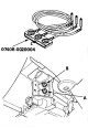
Checking the automatic transmission pressure
Note: Beware of spinning wheels when performing the test. Make sure lifts, jacks and safety stands are securely fastened. Warm up the engine to normal operating temperature (the radiator fan should turn on). When...
Note: Beware of spinning wheels when performing the test. Make sure lifts, jacks and safety stands are securely fastened. Warm up the engine to normal operating temperature (the radiator fan should turn on). When...

Testing the gear shift solenoid valves
1. Remove the drain plug (A) and drain the automatic transmission fluid (ATF). 2. Screw the plug into the drain hole, installing a new sealing washer (B). 3. Place a jack under the transmission and lift it up, creating...
1. Remove the drain plug (A) and drain the automatic transmission fluid (ATF). 2. Screw the plug into the drain hole, installing a new sealing washer (B). 3. Place a jack under the transmission and lift it up, creating...

Replacing the gear shift solenoid valves
1. Remove the drain plug (A) and drain the automatic transmission fluid (ATF). 2. Screw the plug into the drain hole, installing a new sealing washer (B). 3. Place a jack under the transmission and lift it up, creating...
1. Remove the drain plug (A) and drain the automatic transmission fluid (ATF). 2. Screw the plug into the drain hole, installing a new sealing washer (B). 3. Place a jack under the transmission and lift it up, creating...

Testing the solenoid valve A for regulating the pressure in the automatic transmission clutches
1. Remove the air cleaner housing. 2. Disconnect the connector from the solenoid valve A for regulating the pressure in the automatic transmission clutches. 3. Measure the resistance of the solenoid valve A for...
1. Remove the air cleaner housing. 2. Disconnect the connector from the solenoid valve A for regulating the pressure in the automatic transmission clutches. 3. Measure the resistance of the solenoid valve A for...

Replacing the solenoid valve A for regulating pressure in automatic transmission clutches
1. Remove the air cleaner housing. 2. Disconnect the connector from the solenoid valve A for regulating the pressure in the automatic transmission clutches. 3. Unscrew the mounting bolts and remove the solenoid valve A...
1. Remove the air cleaner housing. 2. Disconnect the connector from the solenoid valve A for regulating the pressure in the automatic transmission clutches. 3. Unscrew the mounting bolts and remove the solenoid valve A...

Testing of solenoid valves B and C for pressure regulation in automatic transmission clutches
1. Remove the air cleaner housing. 2. Disconnect the connectors from the solenoid valves B and C for regulating the pressure in the automatic transmission clutches. 3. Measure the resistance of the solenoid valves B and...
1. Remove the air cleaner housing. 2. Disconnect the connectors from the solenoid valves B and C for regulating the pressure in the automatic transmission clutches. 3. Measure the resistance of the solenoid valves B and...
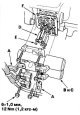
Replacing the solenoid valves B and C for regulating pressure in the automatic transmission clutches
1. Remove the air cleaner housing. 2. Disconnect the connectors from the solenoid valves B and C for regulating the pressure in the automatic transmission clutches. 3. Unscrew the mounting bolts, remove the brackets for...
1. Remove the air cleaner housing. 2. Disconnect the connectors from the solenoid valves B and C for regulating the pressure in the automatic transmission clutches. 3. Unscrew the mounting bolts, remove the brackets for...

Replacing the speed sensors of the main and intermediate shafts
1. Disconnect the connectors from the speed sensors of the main and intermediate shafts. 2. Remove the speed sensors of the main (A) and intermediate (B) shafts. 3. Install a new O-ring (C) onto the input shaft speed...
1. Disconnect the connectors from the speed sensors of the main and intermediate shafts. 2. Remove the speed sensors of the main (A) and intermediate (B) shafts. 3. Install a new O-ring (C) onto the input shaft speed...

Replacing the pressure switch in the 2nd gear clutch
1. Remove the air cleaner housing. 2. Disconnect the connector from the 2nd clutch pressure switch (A). 3. Replace the 2nd clutch pressure switch, then screw in a new one, installing a new sealing washer (B). Tighten...
1. Remove the air cleaner housing. 2. Disconnect the connector from the 2nd clutch pressure switch (A). 3. Replace the 2nd clutch pressure switch, then screw in a new one, installing a new sealing washer (B). Tighten...

Replacing the pressure switch in the 3rd gear clutch
1. Disconnect the connector from the 3rd clutch pressure switch (A). 2. Replace the 3rd clutch pressure switch, then screw in a new one, installing a new sealing washer (B). Tighten the switch by the metal part, not the...
1. Disconnect the connector from the 3rd clutch pressure switch (A). 2. Replace the 3rd clutch pressure switch, then screw in a new one, installing a new sealing washer (B). Tighten the switch by the metal part, not the...

Testing/Replacing ATF Temperature Sensor
1. Remove the drain plug (A) and drain the automatic transmission fluid (ATF). 2. Screw the plug into the drain hole, installing a new sealing washer (B). 3. Place a jack under the transmission and lift it up, creating...
1. Remove the drain plug (A) and drain the automatic transmission fluid (ATF). 2. Screw the plug into the drain hole, installing a new sealing washer (B). 3. Place a jack under the transmission and lift it up, creating...
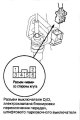
Testing/Replacing O/D Switch
1. Remove the ashtray, front console, heater control panel, driver's side instrument panel lower cover and instrument cluster cover assembly. 2. Disconnect the O/D switch/shift lock solenoid valve/parking pin switch...
1. Remove the ashtray, front console, heater control panel, driver's side instrument panel lower cover and instrument cluster cover assembly. 2. Disconnect the O/D switch/shift lock solenoid valve/parking pin switch...

Checking the ATF fluid level
Note: Do not allow dust or other foreign particles to enter the gearbox. 1. Warm up the engine to normal operating temperature (the radiator fan will turn on), having taken a trip by car 2. Park the car on a level...
Note: Do not allow dust or other foreign particles to enter the gearbox. 1. Warm up the engine to normal operating temperature (the radiator fan will turn on), having taken a trip by car 2. Park the car on a level...

ATF fluid replacement
Note: Do not allow dust or other foreign particles to enter the gearbox. 1. Warm up the gearbox to normal operating temperature (the radiator fan will turn on), having taken a trip by car. 2. Park the car on a level...
Note: Do not allow dust or other foreign particles to enter the gearbox. 1. Warm up the gearbox to normal operating temperature (the radiator fan will turn on), having taken a trip by car. 2. Park the car on a level...

Transfer case
Checking the transfer case 1. Raise the vehicle and support it securely. 2. Shift the gearbox to the [N] position. 3. Apply marks (A) to the propeller shaft (B) and the transfer case connecting flange (C). 4. Separate...
Checking the transfer case 1. Raise the vehicle and support it securely. 2. Shift the gearbox to the [N] position. 3. Apply marks (A) to the propeller shaft (B) and the transfer case connecting flange (C). 4. Separate...

Removal the transfer case assembly
1. Raise the vehicle and support it securely. 2. Remove the drain plug (A) and drain the transmission fluid (ATF). Screw the plug into the drain hole, installing a new sealing washer (B). 3. Apply marks (A) to the...
1. Raise the vehicle and support it securely. 2. Remove the drain plug (A) and drain the transmission fluid (ATF). Screw the plug into the drain hole, installing a new sealing washer (B). 3. Apply marks (A) to the...

Installing the transfer case assembly
1. Thoroughly clean the areas where the transfer case assembly and transmission meet with solvent or carburetor cleaner and dry with compressed air. Then apply transmission fluid to the contact areas. When installing...
1. Thoroughly clean the areas where the transfer case assembly and transmission meet with solvent or carburetor cleaner and dry with compressed air. Then apply transmission fluid to the contact areas. When installing...

Removal the gearbox
1. Raise the vehicle and support it securely. 2. Remove the mud deflector. 3. Remove the drain plug (A) and drain the transmission fluid (ATF). Screw the plug into the drain hole, installing a new sealing washer (B). 4....
1. Raise the vehicle and support it securely. 2. Remove the mud deflector. 3. Remove the drain plug (A) and drain the transmission fluid (ATF). Screw the plug into the drain hole, installing a new sealing washer (B). 4....
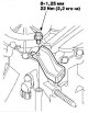
Gearbox installation
1. Install the air cleaner housing mounting bracket. 2. Install the front support. 3. Install the rear support/bracket. Note: 4WD model shown. 2WD model is similar. 4. Install the torque converter assembly (A) onto the...
1. Install the air cleaner housing mounting bracket. 2. Install the front support. 3. Install the rear support/bracket. Note: 4WD model shown. 2WD model is similar. 4. Install the torque converter assembly (A) onto the...
This section is available on: russian, bulgarian, belarusian, ukrainian, serbian, croatian, romanian, polish, slovak, hungarian
Link in different formats to this section
TEXTHTMLBB Code
- General information
- User manual
- Technical data
- Maintenance
- Power unit
- Engine repair
- Lubrication system
- Cooling system
- Exhaust system
- Fuel system
- Engine management
- Engine electrical equipment
- Transmission
- Clutch
- Manual gearbox
- Automatic gearbox
- Rear differential
- Drive shafts
- Chassis and running gear
- Steering
- Front suspension
- Rear suspension
- Brake system
- Body and interior
- Exterior (external elements)
- Interior (internal elements)
- Doors, locks and windows
- General information
- Maintenance
- Tips for car owner
- Power unit
- Engine repair
- Engine overhaul
- Cooling and lubrication system
- Engine electrical equipment
- Control system
- Fuel system
- Transmission
- Clutch and drive shafts
- Car gearbox
- Chassis and running gear
- Front suspension
- Rear suspension
- Steering
- Brake system
- Body and interior
- Body service
- Exterior (external elements)
- Interior (internal elements)
- Electrical equipment
- Equipment and devices
- Electrical circuits