
Manual gearbox of the car Honda CR-V 2
.

Checking and replacing transmission fluid
1. Park the car on a level surface and turn off the engine. 2. Unscrew the plug (A) from the filler hole, remove the washer (B), check the condition of the fluid and make sure that the fluid level (C) is normal. 3. If...
1. Park the car on a level surface and turn off the engine. 2. Unscrew the plug (A) from the filler hole, remove the washer (B), check the condition of the fluid and make sure that the fluid level (C) is normal. 3. If...

Testing the Reverse Light Switch
1. Disconnect the connector from the reverse light switch (A). 2. Check if there is continuity between contacts No. 1 and No. 2 of the 2-pin connector of the reversing light switch. Conductivity should be present when...
1. Disconnect the connector from the reverse light switch (A). 2. Check if there is continuity between contacts No. 1 and No. 2 of the 2-pin connector of the reversing light switch. Conductivity should be present when...

Removal the gearbox
Note: To avoid damaging the paintwork, cover the fenders with protective towels. 1. Write down the frequencies of the radio stations with fixed tuning. First disconnect the cable from the negative (-) battery terminal,...
Note: To avoid damaging the paintwork, cover the fenders with protective towels. 1. Write down the frequencies of the radio stations with fixed tuning. First disconnect the cable from the negative (-) battery terminal,...

Gearbox installation
1. Make sure that 2 dowel pins are installed in the clutch housing. 2. Apply Urea Grease UM264 (P/N 41211-PY-305) onto the release fork (A) and release bearing (B). Install the release fork and release bearing. 3....
1. Make sure that 2 dowel pins are installed in the clutch housing. 2. Apply Urea Grease UM264 (P/N 41211-PY-305) onto the release fork (A) and release bearing (B). Install the release fork and release bearing. 3....

Gearbox disassembly — clutch housing
4WD model 1. Differential assembly 2. Flange bolt 10mm: 44 Nm (4.5 kgf·m) 3. Transfer case assembly 4. O-ring seal: Replace. 5. Mounting pin 10x20mm 6. Shift forks assembly 7. Flange bolt 6x 1.0 mm: 12 Nm (1.2 kgf·m) 8....
4WD model 1. Differential assembly 2. Flange bolt 10mm: 44 Nm (4.5 kgf·m) 3. Transfer case assembly 4. O-ring seal: Replace. 5. Mounting pin 10x20mm 6. Shift forks assembly 7. Flange bolt 6x 1.0 mm: 12 Nm (1.2 kgf·m) 8....

Gearbox disassembly — gearbox housing
Gearbox housing 1. Gearbox housing 2. Washer 10 mm: Replace. 3. Flange bolt 10x1.25 mm: 44 Nm (4.5 kgf·m) 4. Flange bolt 8x1.25mm: 27 Nm (2.8 kgf·m) 5. Gearbox hanger bracket 6. Lock bolt: 39 Nm (4.0 kgf·m) 7. Oil...
Gearbox housing 1. Gearbox housing 2. Washer 10 mm: Replace. 3. Flange bolt 10x1.25 mm: 44 Nm (4.5 kgf·m) 4. Flange bolt 8x1.25mm: 27 Nm (2.8 kgf·m) 5. Gearbox hanger bracket 6. Lock bolt: 39 Nm (4.0 kgf·m) 7. Oil...

Disassembling the gearbox
Note: Place the clutch housing on two pieces of wood of sufficient thickness so that the secondary shaft does not touch the workbench. 1. Remove the transfer case assembly (A), O-ring (B) and Dowel pin (C) 10x20mm. (4WD...
Note: Place the clutch housing on two pieces of wood of sufficient thickness so that the secondary shaft does not touch the workbench. 1. Remove the transfer case assembly (A), O-ring (B) and Dowel pin (C) 10x20mm. (4WD...

Checking the clearance of the reverse gear shift fork
1. Measure the clearance between the reverse idler gear (A) and the reverse shift fork (B) using a feeler gauge (C). If the clearance exceeds the specified limit, proceed to step 1. 2. Standard 0.20-0.59 mm Limit 1.2 mm...
1. Measure the clearance between the reverse idler gear (A) and the reverse shift fork (B) using a feeler gauge (C). If the clearance exceeds the specified limit, proceed to step 1. 2. Standard 0.20-0.59 mm Limit 1.2 mm...

Checking the gear shift lever clearance
1. Measure the clearance between the gear shift lever (A) and the gear selector lever (B) using a feeler gauge (C). If the clearance exceeds the specified limit, proceed to step 1. 2. Standard (new) 0.05-0.25 mm Limit...
1. Measure the clearance between the gear shift lever (A) and the gear selector lever (B) using a feeler gauge (C). If the clearance exceeds the specified limit, proceed to step 1. 2. Standard (new) 0.05-0.25 mm Limit...

Disassembly/assembly of the shift lever assembly
Before assembly, clean all parts in solvent, dry them and apply lubricant to the contact areas.
Before assembly, clean all parts in solvent, dry them and apply lubricant to the contact areas.

Checking the clearances in the gear shift forks
Note: The synchronizer sleeve and hub must be replaced as a set. 1. Measure the gap between each shift fork (A) and the corresponding synchronizer race (B). If the gap exceeds the specified limit, proceed to step 1. 2....
Note: The synchronizer sleeve and hub must be replaced as a set. 1. Measure the gap between each shift fork (A) and the corresponding synchronizer race (B). If the gap exceeds the specified limit, proceed to step 1. 2....


Checking clearances on the secondary shaft assembly
Note: The synchronizer sleeve and hub must be replaced as a set. 1. Insert the bearing inner race into a cartridge (A) of the appropriate size and press the race onto the secondary shaft (B). 2. Measure the clearance...
Note: The synchronizer sleeve and hub must be replaced as a set. 1. Insert the bearing inner race into a cartridge (A) of the appropriate size and press the race onto the secondary shaft (B). 2. Measure the clearance...
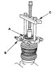
Disassembling and checking the secondary shaft
Disassembling the secondary shaft Note: Remove the synchronizer hubs using a press and steel blocks as shown in the figure. If you use a puller with jaws, you may break the gear teeth. 1. Remove the angular contact ball...
Disassembling the secondary shaft Note: Remove the synchronizer hubs using a press and steel blocks as shown in the figure. If you use a puller with jaws, you may break the gear teeth. 1. Remove the angular contact ball...

Secondary shaft assembly
Note: When assembling, please refer to the exploded view image. 1. Clean all parts in solvent, dry them and apply grease to the contact areas, except for the hubs of the 3rd/4th and 5th gear synchronizers. 2. Install...
Note: When assembling, please refer to the exploded view image. 1. Clean all parts in solvent, dry them and apply grease to the contact areas, except for the hubs of the 3rd/4th and 5th gear synchronizers. 2. Install...

Checking clearances on the intermediate shaft assembly
1. Measure the clearance between the 1st gear pinion (A) and the spacer sleeve (B) using a feeler gauge (C). If the clearance exceeds the specified limit, proceed to step 1. 2. Standard 0.06-0.16 mm Limit 0.25 mm 2....
1. Measure the clearance between the 1st gear pinion (A) and the spacer sleeve (B) using a feeler gauge (C). If the clearance exceeds the specified limit, proceed to step 1. 2. Standard 0.06-0.16 mm Limit 0.25 mm 2....

Disassembling the intermediate shaft
1. Securely clamp the intermediate shaft assembly in a vice using wooden blocks. 2. Unscrew the special bolt (left hand thread). 3. Place the ball bearing (A) on steel blocks (B) and press the intermediate shaft out of...
1. Securely clamp the intermediate shaft assembly in a vice using wooden blocks. 2. Unscrew the special bolt (left hand thread). 3. Place the ball bearing (A) on steel blocks (B) and press the intermediate shaft out of...

Checking the intermediate shaft
1. Check the gear and bearing surfaces for wear and damage, then measure the intermediate shaft at points A, B and C. If any part of the intermediate shaft is less than the specified limit, replace it with a new one....
1. Check the gear and bearing surfaces for wear and damage, then measure the intermediate shaft at points A, B and C. If any part of the intermediate shaft is less than the specified limit, replace it with a new one....

Assembling the intermediate shaft
Note: When assembling, please refer to the exploded view image. 1. Before assembly, clean all parts in solvent, dry them and apply lubricant to the contact areas. 2. Install the spacer sleeve and needle bearing onto the...
Note: When assembling, please refer to the exploded view image. 1. Before assembly, clean all parts in solvent, dry them and apply lubricant to the contact areas. 2. Install the spacer sleeve and needle bearing onto the...
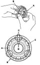
Checking and disassembling the synchronizer cage and hub
1. Check the teeth on all synchronizer hubs and races. If the corners of the teeth are rounded, this indicates wear. 2. Insert each synchronizer hub (A) into its corresponding synchronizer race (B) and check that they...
1. Check the teeth on all synchronizer hubs and races. If the corners of the teeth are rounded, this indicates wear. 2. Insert each synchronizer hub (A) into its corresponding synchronizer race (B) and check that they...

Checking the synchronizer ring and gear
1. Check the synchronizer rings (A) from the inside for wear. Check for wear (not rounded) whether the teeth (B) on the synchronizer rings. An example of the condition of the teeth on the synchronizer rings. 2. Check if...
1. Check the synchronizer rings (A) from the inside for wear. Check for wear (not rounded) whether the teeth (B) on the synchronizer rings. An example of the condition of the teeth on the synchronizer rings. 2. Check if...

Replacing the front bearing and seal
1. Remove the differential assembly. 2. Press out the ball bearing (A) from the clutch housing using a special tool. 3. Remove the oil seal (A) from the clutch side. 4. Press in the new oil seal from the gearbox side...
1. Remove the differential assembly. 2. Press out the ball bearing (A) from the clutch housing using a special tool. 3. Remove the oil seal (A) from the clutch side. 4. Press in the new oil seal from the gearbox side...

Replacing the intermediate shaft bearing
1. Remove the mounting plate (A) from the clutch housing (B). 2. Press out the needle bearing (A) using the special tool, then remove the oil transfer plate C. 3. Install a new oil transfer plate C and a new needle...
1. Remove the mounting plate (A) from the clutch housing (B). 2. Press out the needle bearing (A) using the special tool, then remove the oil transfer plate C. 3. Install a new oil transfer plate C and a new needle...

Adjusting the secondary shaft thrust clearance
1. Remove the 78 mm adjusting washer (A) and the old oil transfer plate M from the gearbox housing (B). 2. Install the 3rd/4th synchronizer hub (A), spacer sleeve (B), 5th synchronizer hub (C), spacer sleeve (D) and...
1. Remove the 78 mm adjusting washer (A) and the old oil transfer plate M from the gearbox housing (B). 2. Install the 3rd/4th synchronizer hub (A), spacer sleeve (B), 5th synchronizer hub (C), spacer sleeve (D) and...

Gearbox assembly
Note: Before assembly, clean all parts in solvent, dry them and apply grease to the contact areas. 1. Install the magnet (A) and differential (B) assembly into the clutch housing. 2. Install the 28mm spring washer (A)...
Note: Before assembly, clean all parts in solvent, dry them and apply grease to the contact areas. 1. Install the magnet (A) and differential (B) assembly into the clutch housing. 2. Install the 28mm spring washer (A)...

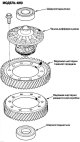

Manual gearbox differential — clearance check
Note: 4WD model shown. 2WD model is similar. 1. Secure the differential assembly to the prisms (A) and install both axle shafts. 2. Measure the clearance between both axle gears (B) and the satellites using a dial...
Note: 4WD model shown. 2WD model is similar. 1. Secure the differential assembly to the prisms (A) and install both axle shafts. 2. Measure the clearance between both axle gears (B) and the satellites using a dial...

Differential manual transmission — replacement of driven gear/cup
1. Unscrew the bolts (left hand thread) crosswise in several passes, remove the transfer case driven gear (A), the final drive driven gear (B) from the differential cup (C). Note: Align the mark on the driven gear and...
1. Unscrew the bolts (left hand thread) crosswise in several passes, remove the transfer case driven gear (A), the final drive driven gear (B) from the differential cup (C). Note: Align the mark on the driven gear and...

Transfer case repair
Transfer case disassembled 2. Measure the clearance in the transfer case gear. Standard: 0.06-0.16mm Measuring the total starting torque 3. Rotate the coupling flange several times to seat the tapered roller bearing. 4....
Transfer case disassembled 2. Measure the clearance in the transfer case gear. Standard: 0.06-0.16mm Measuring the total starting torque 3. Rotate the coupling flange several times to seat the tapered roller bearing. 4....
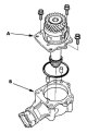
Disassembling the transfer case
1. Remove the transfer case holder assembly (A) from the transfer case housing (B). 2. Cut off the lock nut retaining tabs using a chisel. Do not allow cut off particles to enter the transfer case driven gear. 3. Secure...
1. Remove the transfer case holder assembly (A) from the transfer case housing (B). 2. Cut off the lock nut retaining tabs using a chisel. Do not allow cut off particles to enter the transfer case driven gear. 3. Secure...

Disassembling the transfer case holder
1. Cut off the lock nut retaining tabs using a chisel. Do not allow cut off particles to enter the transfer case driven gear. 2. Secure the transfer case shaft (A) with a 14 mm wrench (B) in a vice, then loosen the lock...
1. Cut off the lock nut retaining tabs using a chisel. Do not allow cut off particles to enter the transfer case driven gear. 2. Secure the transfer case shaft (A) with a 14 mm wrench (B) in a vice, then loosen the lock...

Replacing the outer race of the tapered roller bearing of the transfer case holder
Note: Apply transmission fluid to all parts during assembly. 1. Press the tapered roller bearing outer race (A) and 76 mm thrust washer (B) out of the transfer case holder. 2. Press the 76mm thrust washer (A) into the...
Note: Apply transmission fluid to all parts during assembly. 1. Press the tapered roller bearing outer race (A) and 76 mm thrust washer (B) out of the transfer case holder. 2. Press the 76mm thrust washer (A) into the...

Replacing the transfer case drive gear bearing
Note: Apply transmission fluid to all parts during assembly. 1. Press the tapered roller bearing (A) out of the transfer case pinion gear (B) using a bearing separator (C), a special tool and a press. 2. Press a new...
Note: Apply transmission fluid to all parts during assembly. 1. Press the tapered roller bearing (A) out of the transfer case pinion gear (B) using a bearing separator (C), a special tool and a press. 2. Press a new...

Replacing the Transfer Case Driven Gear Bearing
Note: Apply transmission fluid to all parts during assembly. 1. Press the tapered roller bearing (A) out of the transfer case driven gear (B) using a bearing separator (C), adapter (D) and a press. 2. Press a new...
Note: Apply transmission fluid to all parts during assembly. 1. Press the tapered roller bearing (A) out of the transfer case driven gear (B) using a bearing separator (C), adapter (D) and a press. 2. Press a new...

Replacing the outer ring of the transfer case bearing
Note: Apply transmission fluid to all parts during assembly. Replace the tapered roller bearing and bearing outer race as a set. 1. Press the tapered roller bearing outer race (A) out of the transfer case housing (B) by...
Note: Apply transmission fluid to all parts during assembly. Replace the tapered roller bearing and bearing outer race as a set. 1. Press the tapered roller bearing outer race (A) out of the transfer case housing (B) by...

Transfer case assembly
When performing the assembly, please consider the following: During assembly of the transfer case assembly: Check and adjust the contact patch of the transfer case gear teeth. Measure and adjust the clearance in the...
When performing the assembly, please consider the following: During assembly of the transfer case assembly: Check and adjust the contact patch of the transfer case gear teeth. Measure and adjust the clearance in the...

Selection of transfer case thrust washers
Selection of thrust washer 35 mm 1. Select a 35mm thrust washer when replacing the transfer case driven gear shaft or the tapered roller bearing on the transfer case driven gear shaft. Calculate the thickness of the...
Selection of thrust washer 35 mm 1. Select a 35mm thrust washer when replacing the transfer case driven gear shaft or the tapered roller bearing on the transfer case driven gear shaft. Calculate the thickness of the...
This section is available on: russian, bulgarian, belarusian, ukrainian, serbian, croatian, romanian, polish, slovak, hungarian
Link in different formats to this section
TEXTHTMLBB Code
- General information
- User manual
- Technical data
- Maintenance
- Power unit
- Engine repair
- Lubrication system
- Cooling system
- Exhaust system
- Fuel system
- Engine management
- Engine electrical equipment
- Transmission
- Clutch
- Manual gearbox
- Automatic gearbox
- Rear differential
- Drive shafts
- Chassis and running gear
- Steering
- Front suspension
- Rear suspension
- Brake system
- Body and interior
- Exterior (external elements)
- Interior (internal elements)
- Doors, locks and windows
- General information
- Maintenance
- Tips for car owner
- Power unit
- Engine repair
- Engine overhaul
- Cooling and lubrication system
- Engine electrical equipment
- Control system
- Fuel system
- Transmission
- Clutch and drive shafts
- Car gearbox
- Chassis and running gear
- Front suspension
- Rear suspension
- Steering
- Brake system
- Body and interior
- Body service
- Exterior (external elements)
- Interior (internal elements)
- Electrical equipment
- Equipment and devices
- Electrical circuits