
Note: Keep the timing chain away from magnetic field.
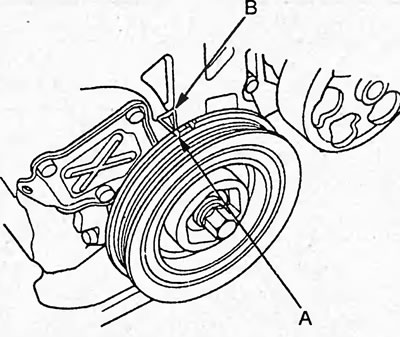
1. Turn the crankshaft pulley and set it so that the TDC mark (A) on the pulley is aligned with the reference mark (B), as shown in the figure.
2. Remove the front wheels.
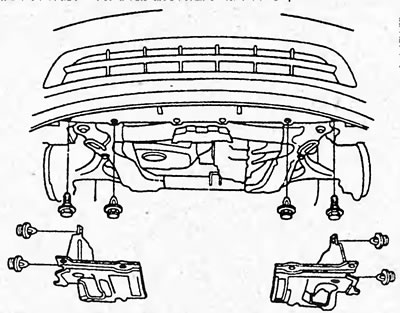
3. Remove the lower protection.
4. Remove the accessory drive belt.
5. Remove the cylinder head cover (see section "Checking and adjusting thermal clearances in the valve drive").
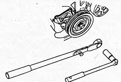
6. Holding the crankshaft pulley from turning with a special tool, unscrew the pulley mounting bolt.
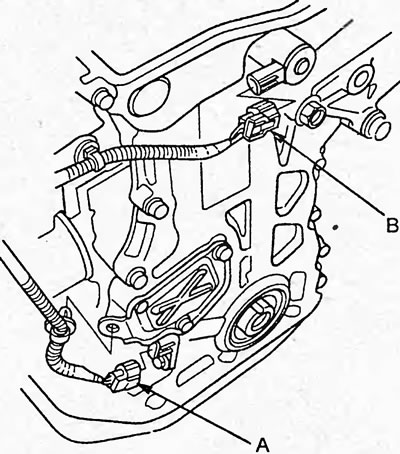
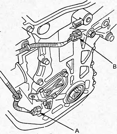
7. Disconnect the connectors of the crankshaft position sensor (A) and the variable valve timing (VTC) valve (B).
8. Jack up the engine. Place a wooden block between the jack foot and the engine.
Note: Do not place the jack in the center of the oil pan to avoid damaging the pan.
9. Remove the front engine mount bracket.
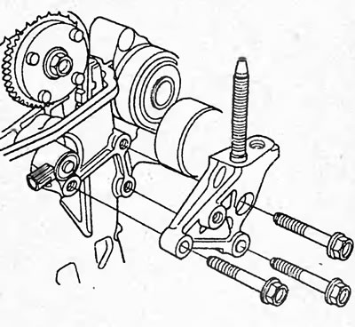
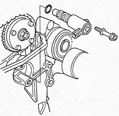
10. Remove the variable valve timing (VTC) valve.
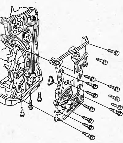
11. Remove the timing chain cover by unscrewing the mounting bolts
12. Temporarily install the crankshaft pulley and tighten the mounting bolt.
13. If necessary, remove the timing chain tensioner service cover from the timing chain.
14. Turn the crankshaft pulley counterclockwise, thereby creating pressure in the tensioner, causing the tensioner piston to be pressed into the tensioner.

15. Align the hole in the locking plate with the hole in the tensioner, insert the pin into the holes
 1.5 mm (A) and turn the crankshaft pulley* clockwise, locking the tensioner.
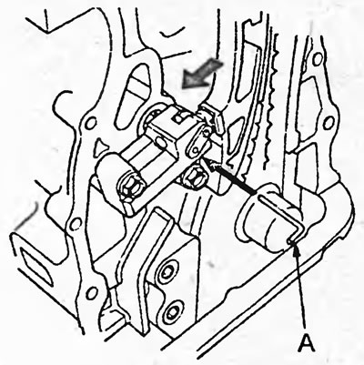
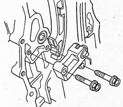
16 Remove the timing chain tensioner.
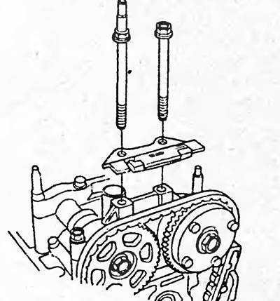
17. Remove the upper timing chain guide, timing chain guide (A) and timing chain tensioner guide (B).

18. Remove the timing chain.
Installation
1. Set the crankshaft pulley to TDC. Align the mark (A) on the crankshaft pulley with the pointer (B) on the cylinder block.
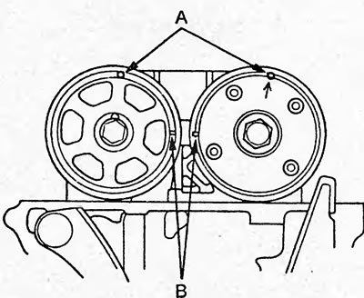
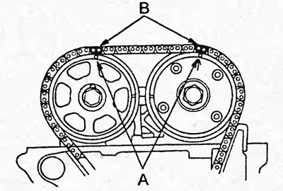
2. Set the piston of the first cylinder to the TDC of the compression stroke. In this case, the holes (A) on the variable valve timing (VTC) coupling and the exhaust camshaft sprocket should be directed upwards, and the TDC marks (B) should be directed towards each other.
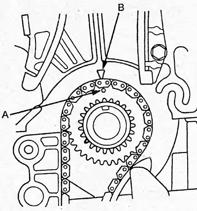
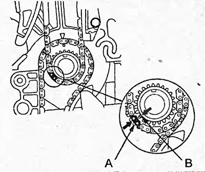
3. Install the chain on the crankshaft sprocket with the colored link (A) opposite the mark (B).
4. Install the chain onto the exhaust camshaft sprockets (A) and the variable valve timing (VTC) clutch with two colored links (B) as shown in the illustration.
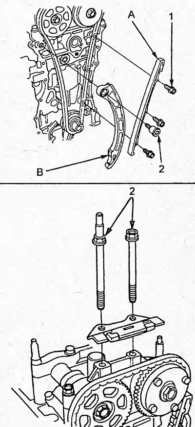
5. Install the timing chain guide, timing chain guide (A) and timing chain tensioner guide (B).
Tightening torque:
- bolt "1" - 12 Nm
- bolt "2" - 22 Nm
Note: Tightening torque for bolts "2" applies to both figures.
6. Install the timing chain tensioner and tighten the mounting bolts.
Tightening torque - 25 Nm

7. Remove the pin from the tensioner.
8. Check the front crankshaft oil seal, replace if necessary.
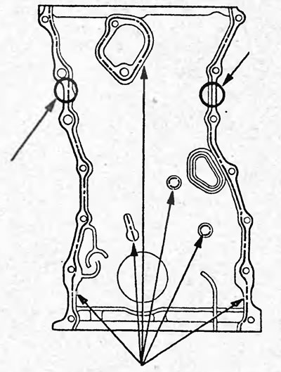
9. Remove any old sealant from the contact surfaces of the timing chain cover and the cylinder block. Clean the contact surfaces.
10. Apply sealant to the contact surfaces of the cylinder block and timing chain cover as shown in the figure.
Note: The parts must be installed within the time specified in the sealant application instructions. Otherwise, the sealant must be removed and reapplied.
11. Clean the contact surfaces of the timing chain tensioner and the access cover, if removed.
12. (If the technological cover was removed) Apply sealant to the contact surface of the process cover as shown in the figure. Install the process cover.
Tightening torque - 12 Nm
Note: The parts must be installed within the time specified in the sealant application instructions. Otherwise, the sealant must be removed and reapplied.
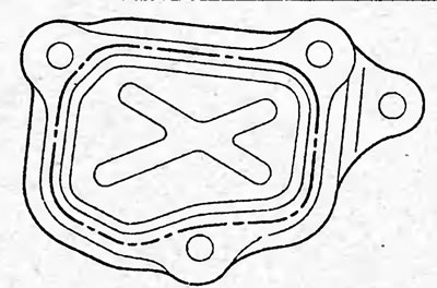
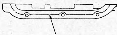
13. Apply sealant to the mating surfaces of the timing chain cover and oil pan as shown in the figure.
Note: The parts must be installed within the time specified in the sealant application instructions. Otherwise, the sealant must be removed and reapplied.
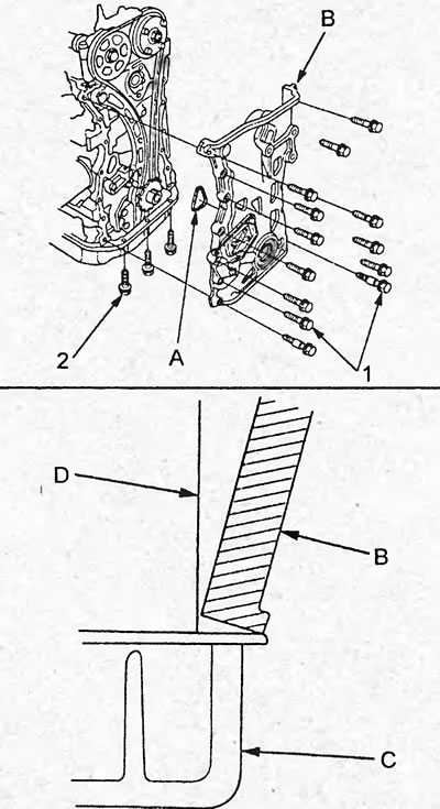
14. Install a new O-ring (A) onto the timing chain cover, align the surface of the timing chain cover (B) with the surface of the oil pan (C), and install the cover onto the cylinder block (D).
Tightening torque:
bolts "1" and "2" - 12 Nm
15. Install the variable valve timing (VTC) valve with a new O-ring and tighten the valve mounting bolt.
Tightening torque - 12 Nm

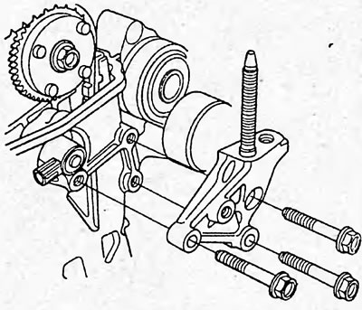
16. Install the front engine mount bracket.
Tightening torque - 44 Nm
17. Connect the connectors of the crankshaft position sensor (A) and the variable valve timing (VTC) valve (B).
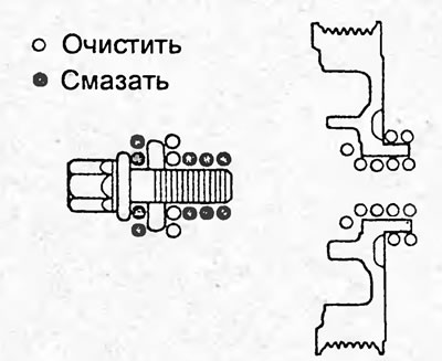
18. Clean the crankshaft pulley and pulley mounting bolt. Apply a coat of grease to the mounting bolt as shown in the figure.
19. Install the crankshaft pulley and, holding it with a special tool, tighten the mounting bolt.
Tightening torque: 245 Nm
20. Install the cylinder head cover (see section "Checking and adjusting thermal clearances in the valve drive").
21. Install the attachment drive belt and adjust its tension.
22. Install the intake manifold cover.
Tightening torque - 12 Nm
23. Install the lower protection and wheels.