
Note: Checking clearances should be performed at engine temperature below 10-40°C.
1. Remove the ignition coil cover and remove the four ignition coils.
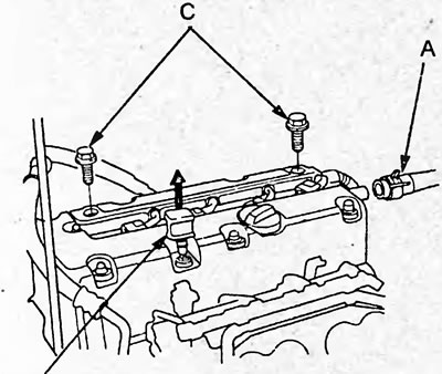
2. Disconnect the inlet hose (A), remove the wire harness bracket by unscrewing the mounting bolts (C) and remove the oil dipstick (B).
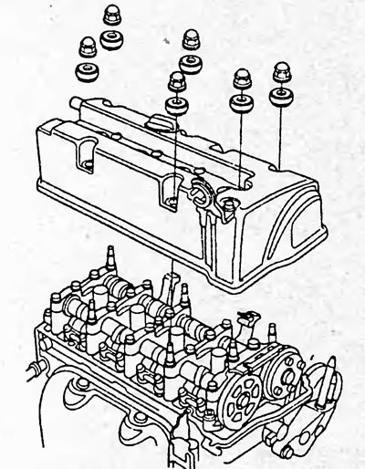
3. Remove the cylinder head cover.
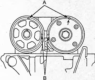
4. Set the piston of the first cylinder to the TDC of the compression stroke. In this case, the holes (A) on the variable valve timing (VTC) coupling and the exhaust camshaft sprocket should be directed upwards, and the TDC marks (B) should be directed towards each other.
5. Insert the feeler gauge (A) between the adjusting screw and the end of the valve. Move the feeler gauge back and forth until a slight resistance is felt.
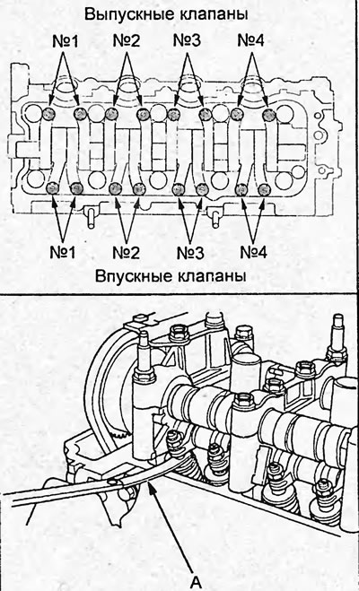
6. If there is a lot of resistance or no resistance, loosen the lock nut (A) and adjust the clearance with the adjusting screw.
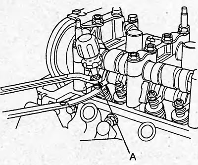
Note: The cylinder head is equipped with 3 types of VTEC rocker arm assemblies (see section "Cylinder head").
Gap:
Rocker arm blocks types 1 and 2:
- inlet - 0.21 - 0.25 mm
- release - 0.28 - 0.32 mm
Rocker arm block type 3:
- inlet - 0.21 - 0.25 mm
- release - 0.25 - 0.29 mm
7. Tighten the lock nut and recheck the clearance. Adjust it if necessary.
Tightening torque:
Rocker arm block type 3 - 20 Nm
Other types:
- intake - 20 Nm
- release - 14 Nm
8. Turn the crankshaft 180° and set the piston of the third cylinder to TDC of the compression stroke. In this case, the holes on the coupling and sprocket should lie in the plane of the cylinder head.
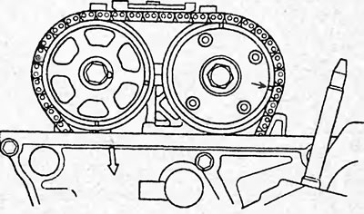
9. Check and, if necessary, adjust the clearance in the valve drive of the third cylinder.
10. Similarly, check the clearance in the drive of the fourth and then the second cylinders, setting the piston of the corresponding cylinder to TDC of the compression stroke.
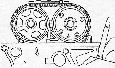
Position of marks when checking the clearance in the valves of the fourth cylinder.
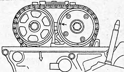
Position of marks when checking the clearance in the valves of the second cylinder.
11. Install the cylinder head cover.
a) Clean the contact surfaces of the cover gasket and the cylinder head cover and the cylinder head.
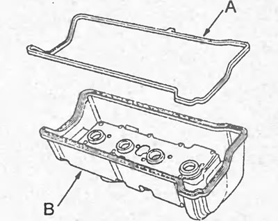
b) Install the cylinder head cover gasket (A) onto the cylinder head cover (B).
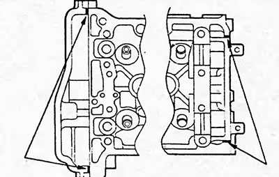
c) Apply a layer of sealant to the cylinder head as shown in the figure.
Note: The parts must be installed within the time specified in the sealant application instructions. Otherwise, the sealant must be removed and reapplied.
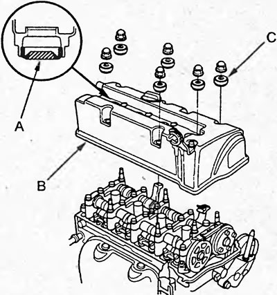
d) Install the spark plug seals (A) onto the spark plug tubes in the cylinder head cover (B) and install the cylinder head cover onto the cylinder head, install the washers (C).
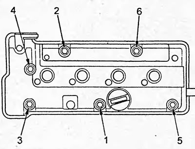
d) Tighten the cylinder head cover mounting bolts in 2-3 passes in the sequence shown in the figure.
Tightening torque - 10 Nm
12. Next, install the parts in the reverse order of removal.
The original is located on the website HondaBook.ru