


Contents: Examination ⇊ Replacement ⇊
Warning! The models of vehicles covered in this manual are equipped with a supplemental restraint system (SRS). Before performing any work near the air bag unit, steering column or instrument panel, turn off the SRS to avoid injury from accidental deployment (see Section Airbags - General Information). The SRS circuit wiring is easily identified by the yellow color of the insulation.
Remove the steering column covers and knee support (see Chapter Body).
Examination
1. Disconnect the negative cable from the battery first, then the positive cable.
Warning! If the car stereo system is equipped with a security code, make sure you have the correct combination to activate the audio system before disconnecting the battery!
2. Remove the lower section of the instrument panel from the driver's side of the vehicle (see Chapter Body). Following the wiring harness from the ignition switch down the steering column to the left junction box, disconnect the electrical connector.
3. Check the connector for continuity between the contact terminals in each ignition key position.

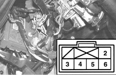
4. If any abnormalities in conductivity distribution are detected, replace the switch.
5. Make sure the lock cylinder fits tightly in all key positions and that the markings are positioned correctly. A worn lock will need to be replaced.
Replacement
Ignition switch
1. Disconnect the negative cable from the battery first, then the positive cable.
Warning! If the car stereo system is equipped with a security code, make sure you have the correct combination to activate the audio system before disconnecting the battery!
2. Remove the upper and lower sections of the steering column cover (see Chapter Body).
3. Insert the key into the lock and turn it to the LOCK position.
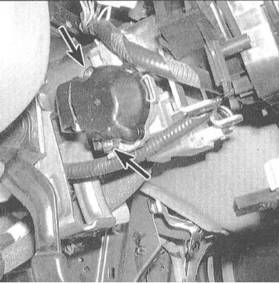
4. Remove the two mounting screws and remove the switch assembly from the steering column.
Lock cylinder
1. Remove the upper and steering column covers and the lower instrument panel trim section (see Chapter Body).
2. Loosen the mounting nuts and lower the column. If the vehicle is equipped accordingly, disconnect the connectors of the electrical wiring of the start immobilization assembly.
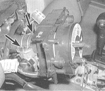
3. The lock assembly is secured to the column with two shear head bolts that need to be drilled out (use a 4.8 mm drill bit).
4. Loosen the clamp and remove the lock assembly cylinder from the steering column. If the vehicle is equipped with the appropriate equipment, remove the starter immobilizer unit from the old cylinder. Transfer the immobilizer to the new cylinder.
Note: If the start immobilizer is replaced for any reason, the control module (PCM) must be reprogrammed at a service station.
5. Place the replacement cylinder in its original position (without a key) and tighten the new mounting bolts securely.
6. Insert the key into the cylinder and check that the assembly is functioning properly.
7. Tighten the mounting bolts until their heads are sheared off. If the vehicle is equipped with the appropriate equipment, connect the electrical wiring to the start immobilizer device.
8. Further assembly is carried out in the reverse order of dismantling of the corresponding components.
9. Finally, connect the battery (first the positive wire, then the negative).