
Contents: General information ⇊ Checking for voltage in the circuit ⇊ Finding the Causes of a Short Circuit ⇊ Search for ground faults ⇊ Search for chain breaks ⇊ Electrical Connectors - General…⇊
Warning! The procedures described below allow for general diagnostics of the main electrical circuits, but should not be used to check vulnerable electrical systems (such as ABS), in particular, those that include electronic control modules (ECUs).
General information
A typical electrical circuit consists of an electrical consumer (working component), a set of switches, relays, actuators, fuses, fuse links/circuit breakers related to the operation of the component, as well as the connecting wiring, its terminals and connectors. To facilitate the diagnostic procedures in Section Electrical connection diagrams this Chapter provides diagrams of electrical connections of various electrical systems of the vehicle.
Before you start looking for the reasons for the failure of a failed power consumer, carefully study the corresponding electrical circuit, try to imagine as clearly as possible the operating principle of the components included in the suspected circuit. The list of possible reasons for failure can be minimized by excluding from it properly functioning components related to the operation of the circuit being checked. In case of simultaneous malfunction of several components, the most likely cause of failure is the failure of a fuse/fuse link common for the corresponding circuits, or a grounding fault.
Most often, electrical equipment failures are explained by simple reasons, such as damage from corrosion or loose terminal connections, failure of a fuse or fusible link, failure of a relay, etc. Before you start looking for internal defects of the actual failed component, carefully check the condition of all fuses, connectors and connecting wires related to its operation. To determine the list of units and terminal connections to be checked, study the corresponding electrical connection diagram.
Diagnostic equipment needed to troubleshoot electrical equipment includes a multi-function circuit meter/voltmeter (for some tests, a 12-volt lamp with a set of connecting wires will also work), a test lamp with an individual power source (sometimes also called a conductivity meter), an ohmmeter, a power supply with a set of connecting wires, and a set of jumper wires equipped with various types of connecting terminals and, preferably, a built-in circuit breaker or fuse (to bypass suspected circuit sections or electrical components). Before using diagnostic equipment, carefully study the electrical connection diagram of the components of the corresponding circuit (see Electrical Wiring Diagrams - General Information).
To find the cause of an unstable failure (faults of this kind are usually associated with oxidation of contact terminals or loosening of the terminal connections of electrical wiring) a simple circuit test can be performed by twitching various sections of the wiring of the corresponding circuit, as a result of which the defective section of the circuit is localized. This test can be performed together with any of those listed below in the corresponding subsections.
In addition to problems associated with poor electrical connections, the most likely and frequently occurring failures of electrical circuits include breaks and short circuits in the circuit.
A circuit break is usually caused by mechanical damage to the conductive wires or disconnection of the contact terminals, which leads to the opening of the electrical circuit and the cessation of circulation of electric current in it. As a result of a circuit break, its working component stops functioning, but the corresponding fuses/fuse links do not fail.
A short circuit is a short circuit in the electrical wiring that is not provided for by the design of the circuit. In this case, the current begins to circulate along the shortest path, usually going to ground. Short circuits are most often associated with a violation of the integrity of the insulation of the electrical wiring and inevitably lead to the failure of the corresponding fuses/fuse links.
Checking for voltage in the circuit
Checking for voltage is a standard check when any electrical consumer fails. Connect one lead of a circuit tester or voltmeter to the negative battery terminal or any reliable ground point on the vehicle's chassis/engine. Connect the other lead of the tester to a terminal connection of the circuit being tested, preferably the one closest to the battery or fuse. Apply power to the circuit. Remember that some circuits are only energized in certain ignition switch positions. If voltage is present (the meter lamp turns on, or the corresponding reading is recorded on the voltmeter indicator), this means that the section of the circuit between the tested terminal connection and the battery is intact.
Continue testing in this manner, moving from one terminal connection in the circuit to the next, moving away from the battery/fuse. The faulty section of the circuit will be located between the point where the meter registers no voltage and the previously tested and working terminal connection. The most common cause of failure is a broken wiring or oxidation/loosening of the terminal connection.
Finding the Causes of a Short Circuit
First of all, disconnect the electrical consumer of the circuit being tested (consumers of electrical energy, or the useful load of a circuit, are components whose operation consumes the current circulating in the circuit, such as lamps, electric motors, heating elements, etc.). Remove the fuse protecting the circuit being tested and connect a test lamp or voltmeter to its mounting terminals. Apply power to the circuit. Remember that some circuits are powered only in certain positions of the ignition switch. If voltage is present at the fuse terminals, then the circuit is shorted (pull the wiring, as a short circuit can be caused by rubbing of its insulation and can be unstable). If there is no voltage, but the fuse continues to burn out after replacement when power is supplied to the circuit, then there is an internal defect in the power consumer, switch or insulation of the electrical wiring.
Search for ground faults
The negative terminal of the battery is grounded to the "mass", which is the metal of the power unit, chassis and body elements of the car. The electrical circuits of most electrical equipment are constructed in such a way that the wiring is used only to supply power to the consumer from the positive terminal of the battery, while the current is returned to the battery through the metal of the mass. This means that the fastening elements of the consumers of electrical energy form the return part of the electrical circuit. In view of the described situation, loosening of the fastening or corrosion of the supporting elements of the working component of the circuit entails a violation of the correct functioning of the circuit (from the complete failure of the latter to partial failure of various sections of the chain). In particular, as a result of loosening of the fasteners, the brightness of the lighting fixtures may decrease (especially if there is a common ground with another circuit), or the speed of rotation of the electric motor (for example, a windshield wiper drive or a cooling system fan). In this case, the failure of one circuit can cause a malfunction of another, which is not outwardly connected with the failed one. Please note that on many cars, certain units are connected to each other by special grounding buses. Such buses are used in cases where there is no direct contact between the metal parts of the units due to the equipment of the supports with flexible rubber bushings (as, for example, in the supports for attaching the power unit to the vehicle chassis).
To check the integrity of the component grounding, disconnect the battery and connect one of the ohmmeter leads to a known reliable ground point on the vehicle. Connect the other lead of the meter to the ground point of the component being tested. The device should record zero resistance, otherwise, you should check the integrity of the connection (see below).
If you suspect that the quality of the terminal connection is compromised, disassemble the grounding contact unit and clean the mating surfaces of the terminals to bare metal. Try to completely remove all traces of corrosion and dirt, then scrape off the paint with a knife, achieving unambiguous contact of the metal surfaces. When assembling the unit, ensure that the fasteners are tightened securely. To ensure the quality of the electrical connection, place knurled washers between the wiring terminals and the ground contacts. To prevent future corrosion, coat the mated terminal connections with acid-free petroleum jelly or silicone grease. Good products include an aerosol for sealing ignition system components and a water-repellent grease.
Search for chain breaks
Intermittent failures of power consumers are most often associated with a violation of the quality of terminal connections due to oxidation or loosening of fasteners. Often, to bring the component into working condition, it is enough to simply pull the corresponding wiring harness / electrical connector. The easiest way to find a break in the circuit is to check its working areas for conductivity. Disconnect the power supply to the circuit and use a meter equipped with an autonomous power source. Connect the meter wires to both outputs of the circuit being tested (power supply terminal and a well-grounded point). If the device detects the presence of conductivity (zero resistance/tester lamp triggering), therefore, the section of the circuit being tested is in good condition. Otherwise, there is a break. The correct operation of switches can be checked in a similar way.
Electrical Connectors - General Information
Most on-board electrical equipment circuit connectors are made of plastic and are multi-pin. The reliability of the joint of the halves of such connectors is ensured by the snapping of locking tabs built into the locking pins of the plugs. Large connectors, such as some of those located under the dashboard of a car, are most often fastened with through bolts threaded through the center of the plug.
To disconnect connectors equipped with plastic locks, a small screwdriver is usually used, with which the locking tabs should be carefully pressed (first carefully study the design of the mated connector - it is often not easy to determine by eye how its halves are fixed; some connectors are equipped with several locking units). Pull only on the plug, and under no circumstances on the wiring harness, to avoid accidental damage to the contact terminals built into the connector.
Connectors always consist of two halves, the terminals of one of which enter the terminals of the other. When studying schematic images of connectors, try to first determine which of its halves is shown in the illustration - connected to the harness or fixed to the component. Remember that the terminals of one half of the connector are always placed in mirror image in relation to the terminals of the other.
Often, when diagnosing electrical circuit failures, it is necessary to check the voltage at the terminals of the mated connector. During such checks, the probe of the measuring device is inserted into the corresponding terminal on the back side of the plug (see illustration below).
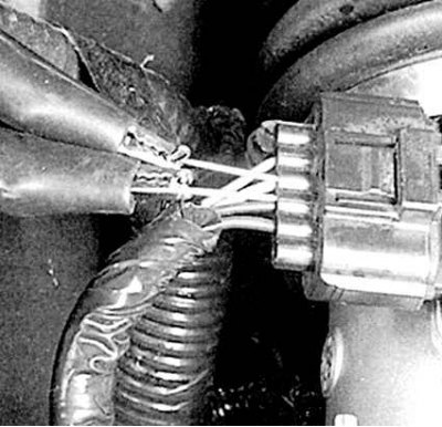
Be careful not to bend or deform the terminals. If the terminal sockets are too small, use a straightened metal paper clip as a feeler gauge, to which you can then attach the meter lead using an alligator clip.
(Information obtained from this source: «HondaBook.ru»)