
Removal and installation of the lower arm
1. Raise the front of the vehicle and place jack stands in the appropriate positions.
2. Remove the front wheels.
3. For HID bulb model: Remove the front headlamp leveling sensor.
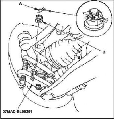
4. Remove lock pin A from lower arm ball joint castle nut, then remove castle nut B.
Note. During installation, tighten the new castle nut, then install the new lock pin.
5. Disconnect the lower ball joint from the cam using the special tool.
6. Remove the mounting nut A of the vibration damper and vibration damper B.
Note. The vibration damper is only on the left side of the lower arm.
During reassembly, use a new vibration damper mounting nut.
 | 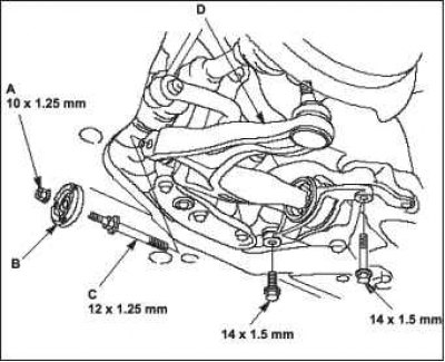 |
7. Turn out bolts of fastening of the lower lever and a special bolt C, then remove the lower lever D.
Note. When reassembling, use new lower arm mounting bolts and a new special bolt.
8. During installation, tighten the mounting bolts and special bolt to the recommended torque. Then install the vibration damper and install the fastening nut A to the recommended torque.
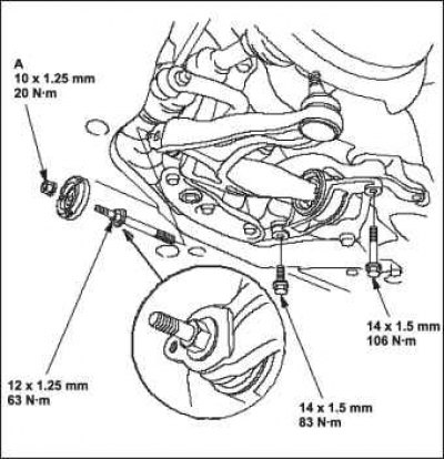
9. Perform the installation operations of the lower arm in reverse order with respect to the removal operations, observing the following.
When installing the steering knuckle, be careful not to damage the protective cover of the ball joint.
Tighten all threaded connections to the recommended torque.
Before connecting the lower ball joint to the cam, remove any remaining grease from the threads and seating surface of the ball joint pin, from the surface of the cam bore, from the threads and mating surface of the castellated nuts.
First assemble all components except the vibration damper and mounting block and lightly tighten the bolts, then raise the suspension to bear the weight of the vehicle before finally tightening the bolts to the recommended torque.
First tighten the castle nut to the lower torque limit, then tighten it just until the notch lines up with the hole in the ball stud. Do not match the slot with the hole by loosening the nut.
Before installing the wheel, clean the mating surface of the brake disc and the inner surface of the bore of the wheel disc.
10. Check wheel alignment and adjust if necessary.
11. For model with HID lamp: follow the headlight position learning procedure.
Bushing replacement
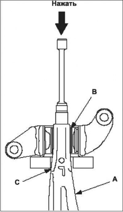
1. Press out the lower arm A with a suitable socket wrench and hydraulic press and remove the lower arm from the bushing B.
Note. Glue protective tape to the lower arm under bush C to prevent damage to the lower arm.
2. Moisten the surface of the new bushing with water.
3. Align the angle of the lower arm A and the mount B of the bushing C. First push the bushing in by hand.
Note. Mounting points of the installed bushing point up and down with respect to the installed lower arm.

4. Press in the 32mm bushing with a socket wrench and a hydraulic press.
5. Adjust the distance between the top of the lower arm and the bushing surface as shown.
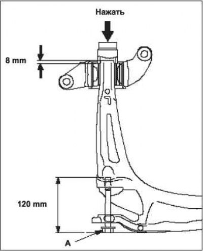
Note. While pressing, hold the lower arm with a suitable flange bolt A.