
Check on the car
1. Perform the procedures specified in the section "Before carrying out repair work".
2. Turn the ignition key to the "OFF" position.
3. Remove the center console.
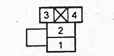
4. Using a jumper, connect terminals "1" and "2" of the main relay No.2 connector.
5. Disconnect the fuel hose from the fuel pipe. Direct the hose into a measuring container.
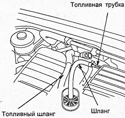
6. Place a suitable vinyl hose on the tube to prevent fuel from splashing out. Point into a measuring container.
7. Turn the ignition key to the "ON" position for 10 seconds.
Productivity in 10 sec. is not less than 270 milliliters.
If necessary, check: wiring harness, fuel filter, fuel lines, fuel pressure regulator.
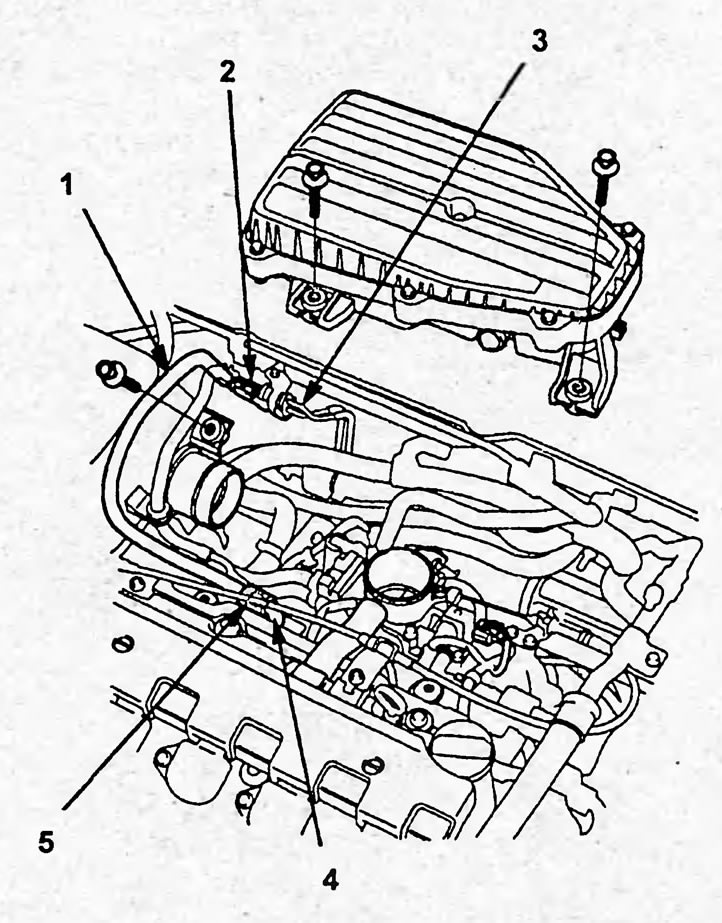
Location of quick release couplings in the engine compartment (engines D15B, D17A). 1 - fuel hose, 2, 5 - quick-release coupling, 3, 4 - fuel pipe.
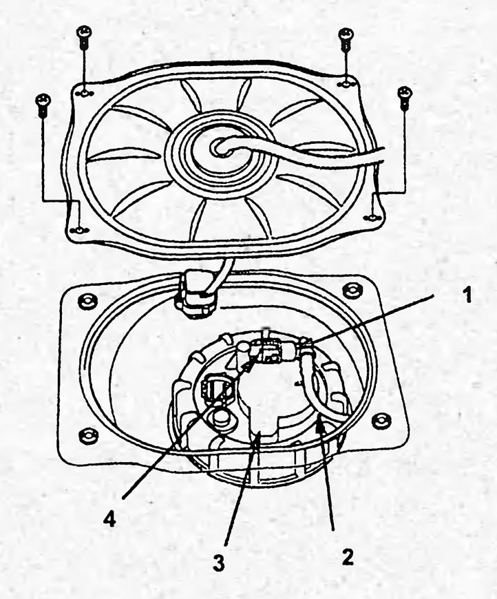
Quick release fuel pump coupling. 1 - quick-release coupling, 2 - fuel hose, 3 - fuel pump, 4 - retainer.
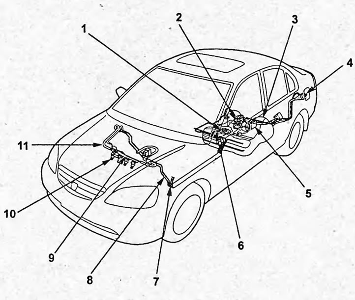
Fuel system (2WD sedan model). 1 - fuel pump, 2 - valve (2-way), 3 - fuel tank, 4 - fuel filler cap, 5 - fuel vapor accumulator, 6, 11 - quick-release coupling, 7 - fuel vapor recovery system tube, 8 - fuel tube, 9 - fuel manifold, 10 - injector.
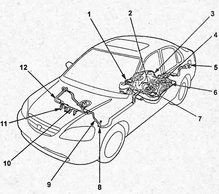
Fuel system (4WD sedan model). 1 - fuel priming, 2, 12 - quick-release coupling, 3 - fuel tank, 4 - fuel vapor accumulator, 5 - fuel filler cap, 6 - valve (2-way), 7 - fuel pump, 8 - fuel vapor recovery system tube, 9 - fuel tube, 10 - fuel manifold, 11 - injector.
Removal and installation
1. Perform the procedures specified in the section "Before carrying out repair work".
2. Unscrew and screw back the fuel filler cap.
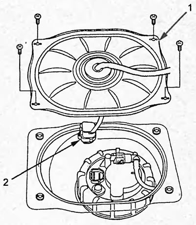
3. Loosen 4 screws and remove the service cover (1). Disconnect the fuel pump connector (2).
4. Disconnect the quick-release coupling of the fuel pipes.
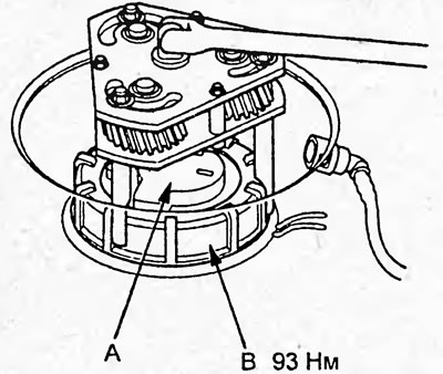
5. Using a special tool, unscrew the nut (B) of the fuel pump (A). Tightening torque 93 N·m
6. (4WD models) Disconnect the hose (B) from the fuel pump.
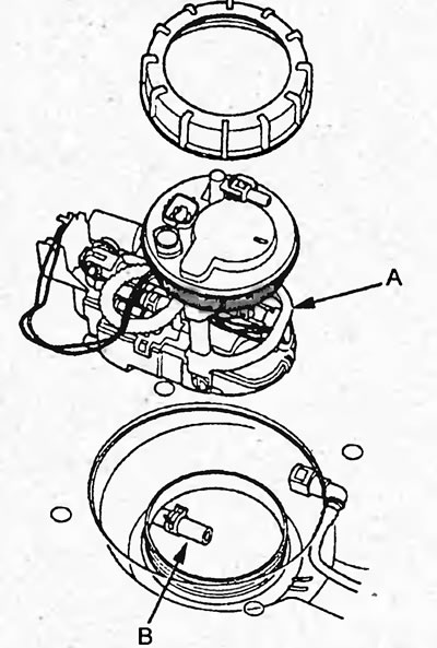
7. Remove the fuel pump.
8. Disassemble and assemble in the order shown in the figure "Disassembling and assembling the fuel pump".
Note:
- Do not damage the fuel level indicator sensor.
- Install new sealing rings when reassembling.
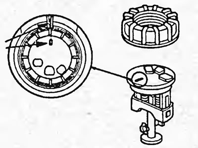
- When assembling, align the marks on the fuel pump.
Checking the additional fuel pump
1. Perform the procedures specified in the section "Before performing repair work".
2. Unscrew and screw back the fuel filler cap.
3. Loosen 4 screws and remove the service cover (1). Disconnect the auxiliary fuel pump connector (2).
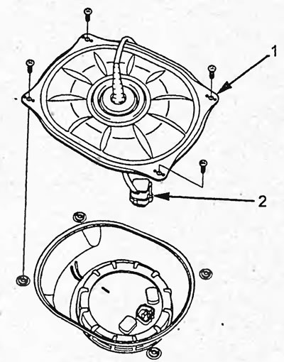
4. Disconnect the quick-release coupling of the fuel pipes.
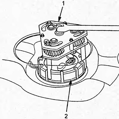
5. Using a special tool, unscrew the nut (B) of the additional fuel pump (A).
Tightening torque - 93 Nm
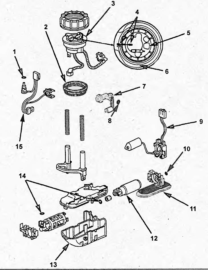
Disassembly and assembly of the fuel pump (2WD models). 1, 2, 8, 10, 14 - sealing ring, 3 - high-pressure fuel filter, 4 - marks, 5 - fuel pump assembly, 6 - fuel tank, 7 - fuel pressure regulator, 9 - fuel level indicator sensor, 11 - low-pressure fuel filter, 12 - fuel pump, 13 - cover, 15 - wiring harness.
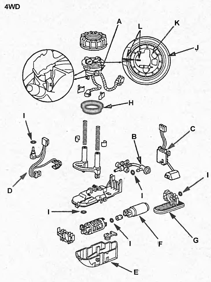
Disassembly and assembly of the main fuel pump (4WD models). A - high pressure fuel filter, B - fuel pressure regulator, C - fuel level indicator sensor, D - wire harness, E - housing, F - fuel pump, G - low pressure fuel filter, H - seal, I - sealing ring, J - fuel tank, K - fuel pump housing assembly, L - marks.
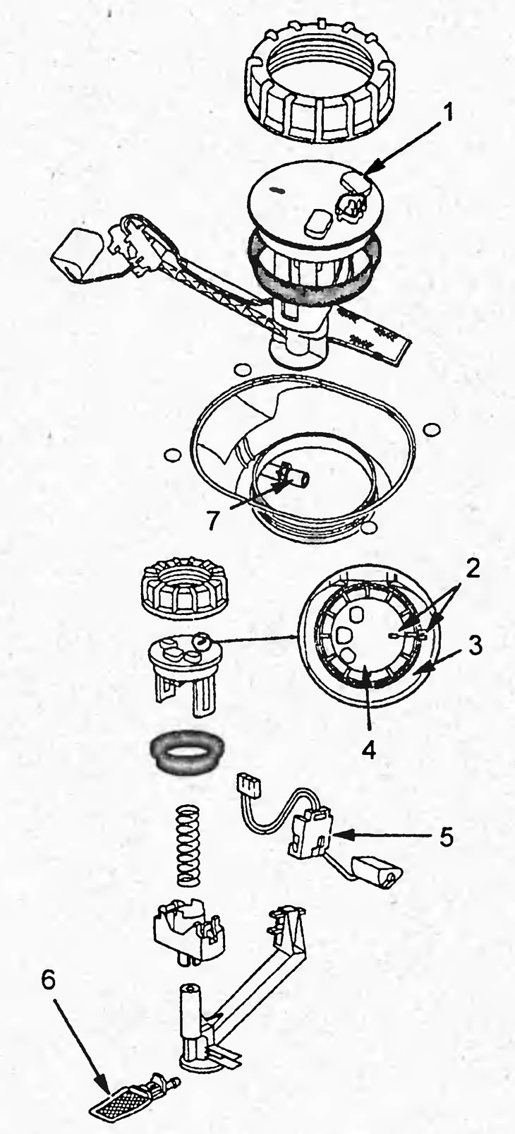
Disassembly and assembly of additional fuel pump (4WD models). 1 - fuel pump, 2 - marks, 3 - fuel tank, 4 - additional fuel pump assembly, 5 - fuel level indicator sensor, 6 - low-pressure fuel filter, 7 - fuel hose.
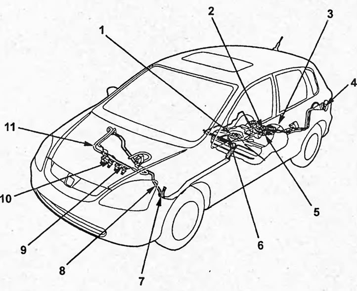
Fuel system (hatchback model 2WD). 1 - fuel pump, 2 - valve (2-way), 3 - fuel tank, 4 - fuel filler cap, 5 - fuel vapor accumulator, 6, 11 - quick-release coupling, 7 - fuel vapor recovery system tube, 8 - fuel tube, 9 - fuel manifold, 10 - injector.
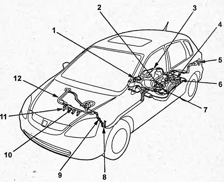
Fuel system (hatchback 4WD models). 1 - fuel priming pump, 2, 12 - quick-release coupling, 3 - fuel tank, 4 - fuel vapor accumulator, 5 - fuel filler cap, 6 - valve (2-way), 7 - fuel pump, 8 - fuel vapor recovery system tube, 9 - fuel tube, 10 - fuel manifold, 11 - injector.
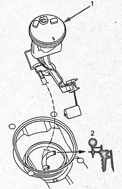
6. Disconnect the hose from the auxiliary fuel pump (1).
7. Connect the hose to the vacuum pump (2).
8. Set the ignition switch to the "OFF" position.
9. Remove main relay #2.
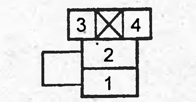
10. Using a jumper, connect terminals "1" and "2" of the main relay No.2 connector.
11. Set the ignition switch to the "ON" position.
12. Measure the vacuum.
Vacuum - > 4.0 kPa (30 mm Hg.)
If necessary, check: low pressure fuel filter of the additional fuel pump, fuel lines, fuel pump.