
Before carrying out repair work
1. Turn the ignition key to the "OFF" position.
2. Remove main relay No.2.
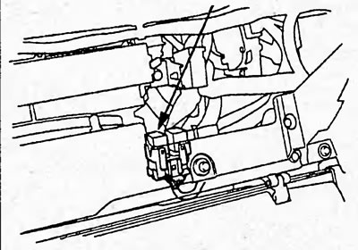
Sedan.
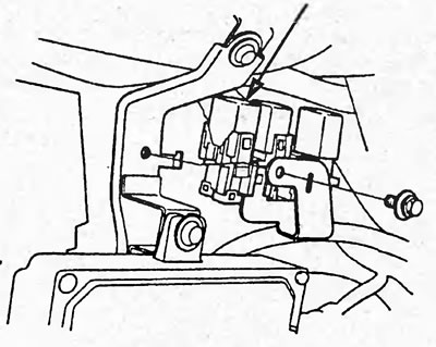
Hatchback.
3. Start the engine.
Note: fault codes P0301, P0302, P0303, P0304 may appear.
4. After the engine stalls, turn the ignition key to the "OFF" position.
5. Unscrew and screw back the fuel filler cap.
6. Disconnect the cable from the negative terminal of the battery.
7. (Sedan) Remove the bracket and covers from the quick release coupling.
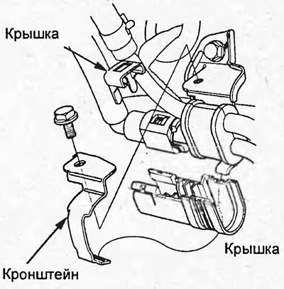
8. (Hatchback) Remove the cover from the quick release coupling.
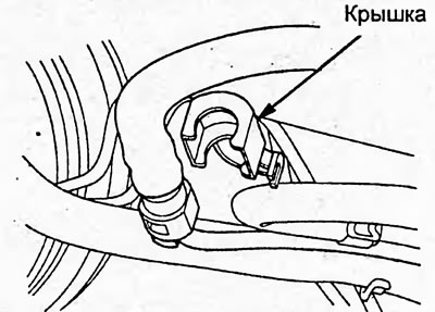
9. Make sure the quick-release coupling is clean. If necessary, gently clean it with a brush.
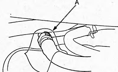
10. Cover the quick-release coupling (A) with a rag.
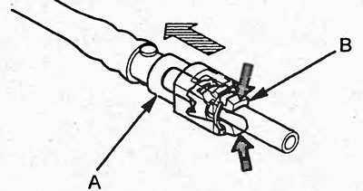
11. Hold the connector (A) with one hand and press the latches (B) with the other. Carefully disconnect the tubes.
Attention:
- Do not use tools when disconnecting.
- If the connector does not disassemble, then push the tubes tightly together and try again.
- Avoid spilling fuel.
- Do not smoke or use open flames when working on the fuel system.
- Avoid contact of gasoline with rubber or leather items.
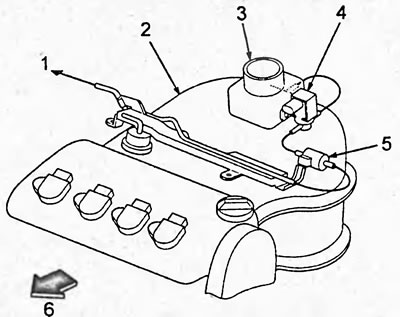
Vacuum line diagram (d17 engine). 1 - to the fuel vapor accumulator; 2 - intake manifold; 3 - throttle body; 4 - fuel vapor accumulator electro-pneumatic valve; 5 - valve; 6- front.
After the repair work has been completed
1. Turn the ignition switch to the "ON" position.
2. Check for fuel leaks within 5 minutes. Repair if necessary.
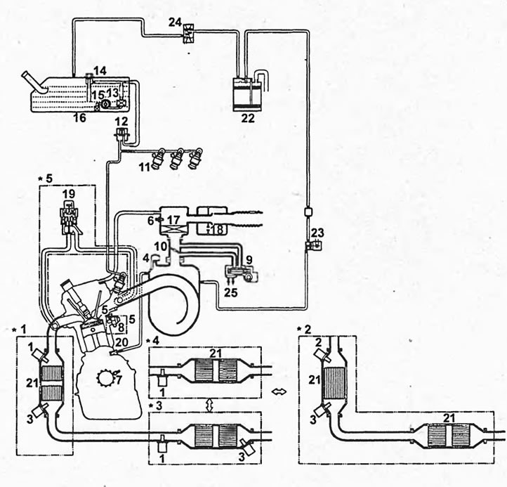
Schematic diagram of the electronic engine control system D17. 1 - oxygen sensor before catalytic converter, 2 - air-fuel ratio sensor, 3 - oxygen sensor after catalytic converter, 4 - intake manifold vacuum sensor, 5 - coolant temperature sensor, 6 - intake air temperature sensor, 7 - crankshaft position sensor, 8 - knock sensor, 9 - idle speed control valve, 10 - throttle body, 11 - injectors, 12 - fuel pressure pulsation damper, 13 - fuel filter, 14 - fuel pressure regulator, 15 - fuel pump, 16 - fuel tank, 17 - air filter, 18 - resonator, 19 - EGR valve, 20 - positive crankcase ventilation valve, 21 - catalytic converter, 22 - fuel vapor canister, 23 - fuel vapor accumulator electro-pneumatic valve, 24 - valve (2-way), 25 - coolant.
Note:
- 1 - 2WD sedan models with D15B SOHC engine.
- 2 - Models with D15B SOHC VTEC engine.
- 3 - Models with D15B SOHC VTEC engine (except 2WD), 2WD models with D17A SOHC VTEC engine.
- 4 - 4WD models, 2WD hatchback models with D15B engine.
- 5 - Models with D15B SOHC VTEC, D17A SOHC VTEC engines.
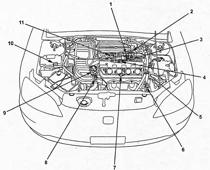
Layout diagram of the electronic control system elements for D15B, D17A engines. 1 - fuel vapor accumulator electro-pneumatic valve, 2 - intake air temperature sensor, 3 - intake manifold vacuum sensor, 4 - throttle position sensor, 5 - camshaft position sensor, 6 - crankshaft position sensor, 7 - knock sensor, 8 - coolant temperature sensor, 9 - exhaust gas recirculation valve, 10 - supply voltage control system unit, 11 - idle speed control system valve.
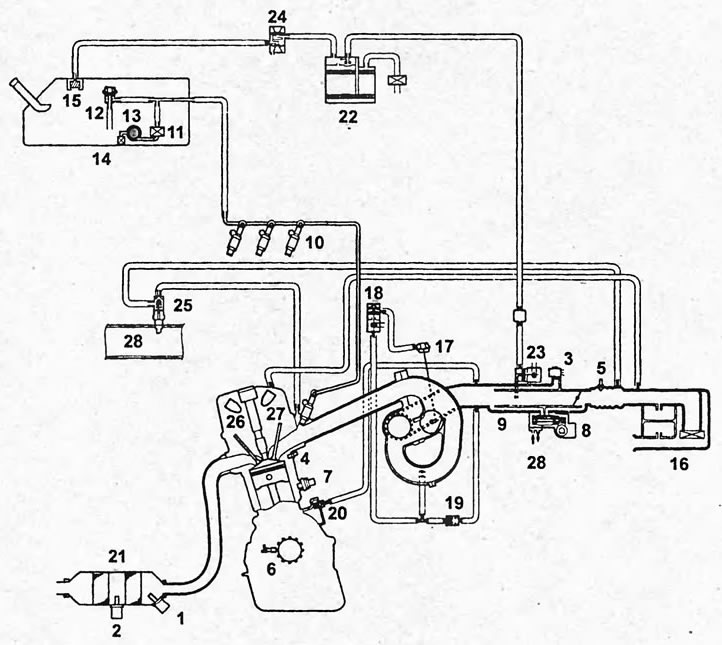
Schematic diagram of the electronic control system of the K20A engine. 1 - air-fuel ratio sensor, 2 - oxygen sensor after catalytic converter, 3 - intake manifold vacuum sensor, 4 - coolant temperature sensor, 5 - intake air temperature sensor, 6 - crankshaft position sensor, 7 - knock sensor, 8 - idle speed control system valve, 9 - throttle body, 10 - injectors, 11 - fuel filter, 12 - fuel pressure regulator, 13 - fuel pump, 14 - fuel tank, 15 - valve, 16 - air filter, 17 - intake manifold variable geometry system actuator, 18 - intake manifold variable geometry system electro-pneumatic valve, 19 - valve, 20 - positive crankcase ventilation system valve, 21 - catalytic converter, 22 - fuel vapor accumulator, 23 - electro-pneumatic valve fuel vapor accumulator, 24 - valve (2-way), 25 - valve for supplying additional air to the injectors, 26 - camshaft position sensor, 27 - camshaft position sensor (VTC), 28 - coolant.
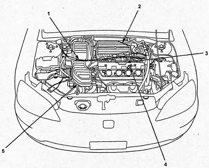
Layout diagram of the electronic engine control system elements D17 (hatchback). 1 - accelerator cable, 2 - air filter, 3 - throttle body, 4 - positive crankcase ventilation valve, 5 - resonator.