
Withdrawal
Attention! The vehicles covered in this manual are equipped with airbags (SRS). When performing any work near the shock sensors, steering column or instrument panel, turn off the SRS (see wiring diagrams at the end of the Chapter Onboard electrical equipment).
1. Disconnect from the battery at first a negative wire, then positive.
Attention! If the stereo system installed in the car is equipped with a security code, before disconnecting the battery, make sure that you have the correct combination to activate the audio system!
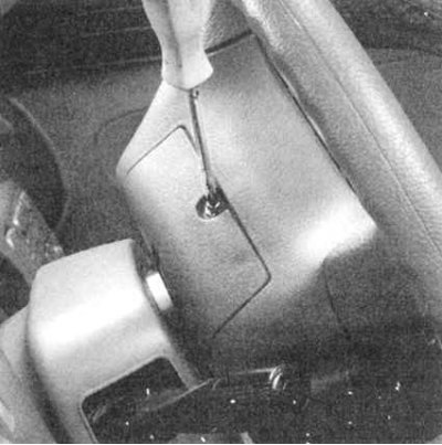
2a. Turn the steering wheel 180°so that the access cover to the inside of the steering wheel is at the top. Remove the cover.
2b. A jumper connector is fixed on its inner side, designed to immobilize the airbag module.
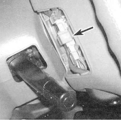
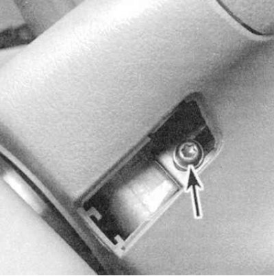
2c. Remove the connector from the latch on the cover (see accompanying illustration).
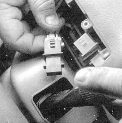
2d. Disconnect the yellow connector of the cable drum of the SRS module and replace its plug with a jumper connector, thereby temporarily immobilizing the airbag module.
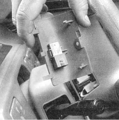
3a. Remove both TORX head screws from the instrument panel side of the steering wheel assembly (see accompanying illustrations).
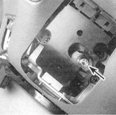
3b. These screws secure the SRS module to the assembly.
4. Remove the module from the steering wheel assembly and stow it in a safe place, laying it face up.
Attention! Try not to turn the module so that it faces you. Never place any foreign objects on top of the module.
5. Disconnect the electrical connectors for the horn button and (with appropriate equipment) tempostat.
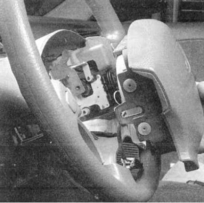
6. Give a nut of fastening of a steering wheel. After removing the nut, mark the position of the steering wheel hub relative to the column shaft (see accompanying illustration).
7. Pulling the wheel strictly parallel to its axis, remove it from the steering shaft. If the wheel does not give in, wiggle it a little.
Attention! Do not allow the column shaft to rotate with the steering wheel removed, as this may damage the cable drum of the SRS module.
Installation
1. Make sure the front wheels of the vehicle are in a straight line.
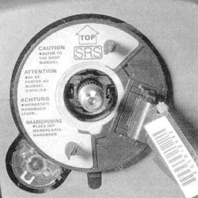
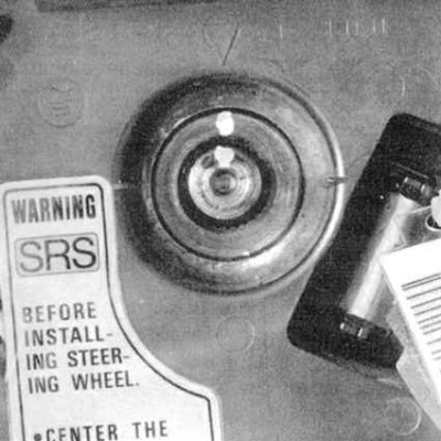
2. Make sure the arrow marked TOP of the SRS cable drum is pointing straight up (see accompanying illustration), - if the camshaft of the column did not rotate after removing the steering wheel, there should be no problems with this issue. If for any reason the shaft did turn, re-align by proceeding as follows:
a) Turn the cable drum clockwise as far as it will go;
b) Rotate the cable drum counterclockwise about two turns until the yellow tooth of the gear aligns with the mark on the cover (only applies to some models), and the marking "TOR" was at the top.
3. Move the steering wheel to its normal position and achieve alignment of the landing marks applied during dismantling (see paragraph 6, Removal). Make sure the column guide pins fit into the mating holes on the back of the steering wheel. Place the wheel hub on the steering shaft stub, screw on the fixing nut and tighten it to the required torque.
4. Connect the horn connectors and (with appropriate equipment) tempostat.
5. Replace the SRS module with new TORX screws. Make sure the screws are tightened to the correct torque. Replace the screw access covers.
6. Remove the jumper connector.
7. Connect the halves of the SRS cable drum connector together.
8. Snap the jumper connector into the retainer on the back of the access cover and install the latter on the steering wheel assembly.