
Testing
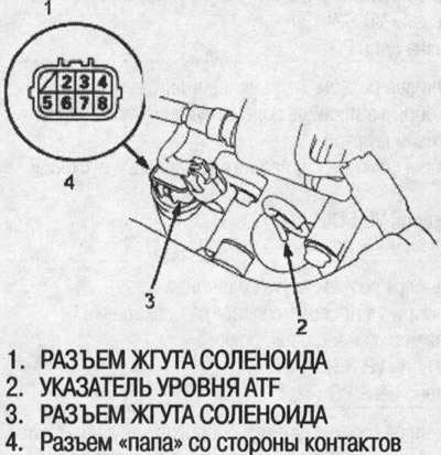
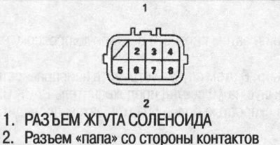
1. Disconnect the 8-pin harness connector from the solenoid.
2. Measure the resistance of the linear shift control solenoid between pins #3 and #7 of the solenoid harness connector.
- Standard: 3.8-6.8 ohms
3. Measure the resistance of the PH-PL linear control solenoid between pins #2 and #6.
- Standard: 3.8-6.8 ohm
4. Measure the resistance of the start clutch linear control solenoid between pins #4 and #8.
- Standard: 3.8-6.8 ohm
5. Measure the resistance of the lockout solenoid between terminal #5 and ground.
- Standard: 11.7-21.0 ohm
6. If either solenoid resistance is out of specification, replace the lower manifold assembly.
7. If the resistance of all solenoids is within limits, then a clicking sound should be heard when the battery is connected to the following pins of the solenoid harness connectors:
Linear shift control solenoid
Pin #3: Battery Positive
Pin #7: Battery Negative
Linear control solenoid PH-PL
Pin #2: Battery Positive
Pin #8: Battery Negative
Clutch linear control solenoid
Pin #4: Battery Positive
Pin #8: Battery Negative
Lockout solenoid
Pin #5: Battery Positive
Ground: Battery negative
8. If clicks are not heard, replace the lower valve manifold assembly.
Note: If replacement of the lower manifold assembly is required, refer to the appropriate section below.