
Contents: Protection from unqualified…⇊ Idle speed adjustments ⇊ Adjusting the minimum idle speed and…⇊ Adjusting the high idle speed ⇊
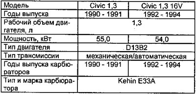
Protection from unqualified interference (filling)
To prevent unqualified interference (or reducing its impact) on the minimum idle speed adjustment screw and the mixture composition adjustment screw (cO content in exhaust gases) safety seals or plugs may be installed.
Idle speed adjustments
Prerequisites
These conditions must be met if it is necessary to check or adjust the idle speed or the mixture composition (cO content in exhaust gases) in these modes. In this case, with any such adjustments, the following conditions must first be observed:
- the engine must be warmed up to normal operating temperature; and the cooling system fan should turn on twice;
- the automatic transmission gear selector must be in neutral position.
Adjusting the minimum idle speed and mixture composition (cO content in exhaust gases) in this mode
Technical conditions:
minimum idle speed
- for models with manual transmission - 800±50 rpm;
- for models with automatic transmission (gear selector is in position "N" or "P") - 1000±50 rpm;
- cO content in exhaust gases - no more than 0.2%.
1. Make sure all auxiliary equipment (energy consumers) off.
2. Connect the tachometer, start the engine and let it idle for 2 minutes.
3. Increase the speed to 3000-3500 rpm and let the engine run at this speed for one minute.
4. Return the engine to natural idle speed and check the speed.
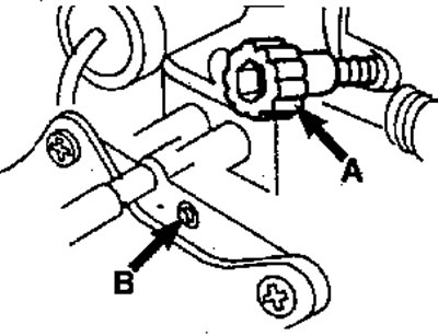
5. If necessary, adjust the rotation speed by turning the throttle stop screw "A". The cooling system fan must be turned off.
Minimum speed adjustment screws (A) and mixture composition (B)
6. Turn off the ignition.
7. Start the engine again and let it idle for 2 minutes.
8. Increase the speed to 3000 -3500 min⁻¹ and let the engine run at this speed for one minute.
9. Return the engine to natural idle mode. The cooling system fan should be turned off.
10. Check the CO content in the exhaust gases and compare its value with the technical specifications.
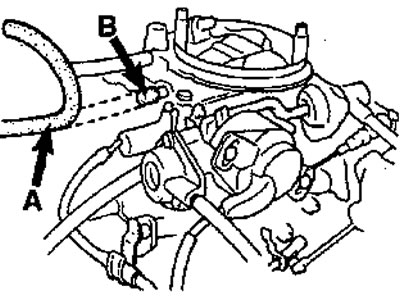
11. If adjustment is necessary, disconnect the vacuum tube "A" and seal the tube "B" of the carburetor.
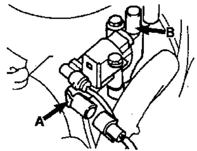
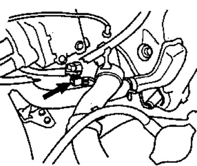
12. Disconnect the multi-pin connector and vacuum tube from the air valve (exhaust manifold air bypass valve) electronically controlled (EACV) and plug valve "A".
Electronically controlled air bypass valve connectors
13. Disconnect the oxygen sensor connector.
14. Turn off the ignition.
15. Start the engine again and let it idle for 2 minutes.
16. Increase the speed to 3000 -3500 min⁻¹ and let the engine run at this speed for one minute.
17. Return the engine to natural idle speed; in this case, the CO content in the exhaust gases should be within 2.5±0.5%.
18. If necessary (if the CO content is outside the specified limits) remove the safety plug and adjust the mixture composition adjustment screw "B" (Fig. 1).
19. Adjust the mixture composition by turning the adjusting screw clockwise to reduce the CO content in the exhaust gases (to lean out the mixture) or counterclockwise to increase it (to enrich the mixture).
20. Connect the multi-pin connector and the vacuum pipe of the electronically controlled air control valve (EACV).
21. Check the natural idle speed (minimum idle speed) and adjust it if necessary.
22. Turn off the ignition.
23. Turn off the fuse "Return" ("BACK UP") for about 10 seconds to reboot ("reset to zero") the control unit.
24. Install new safety plugs ("seals") on the adjusting screws.
Adjusting the high idle speed
Technical conditions:
increased idle speed -3200±500 rpm.
1. Make sure the engine is cold.
2. Disconnect the vacuum line from the high idle speed control relief valve "A" and seal the line "B" with a plug.
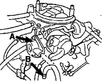
3. Fully open and close the throttle valve to engage the high idle speed control cam.
High Idle Speed Control Cam
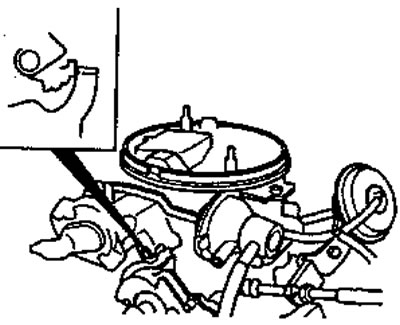
4. Start the engine and compare the increased idle speed value with the specification data,
5. If necessary, adjust the high idle speed by turning the adjusting screw.
High Idle Speed Adjustment Screw
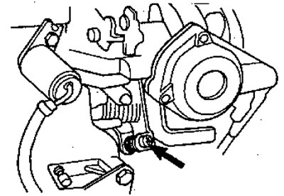
6. Connect the vacuum tube of the high idle speed control cam relief valve and warm up the engine to normal operating temperature.
7. After the engine has warmed up, the speed should decrease to a value less than 1400 min⁻¹, since the unloader valve diverts the air damper rod away from the high idle speed control cam.
8. If the speed does not decrease to the specified level, disconnect the vacuum tube from the relief valve "A".
9. Connect a vacuum gauge to the tube and make sure there is a vacuum.
Connecting a vacuum gauge
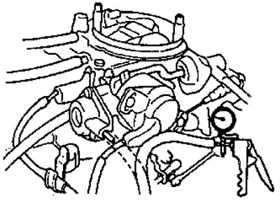
10. If there is no vacuum, check the tube for damage or blockage.
11. If there is a vacuum, it may be due to a faulty unloading valve or a jammed air damper rod.
[The original is located on the website: HondaBook]