
Replacement
Warning: Halogen headlights become very hot, so do not touch them or their connecting parts immediately after turning them off.
1. Remove the front bumper.
2. Remove the mounting bolts.
3. Disconnect each connector, then the headlight/parking signal lamp/turn signal lamp assembly.
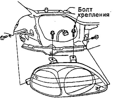
Headlight: 60/55 W; Front parking signal lamp: 5 W; Turn Signal Lamp: 21W
4. Install the headlight in the reverse order of removal.
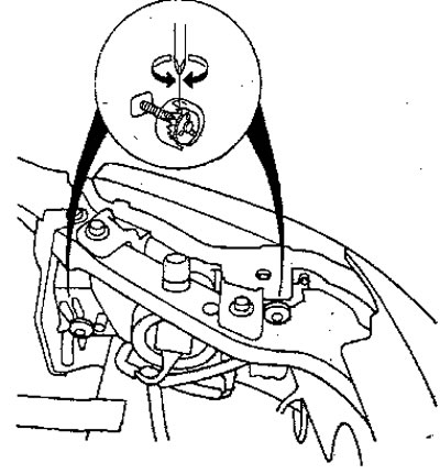
5. Adjust the headlights to local requirements by turning the adjuster.
Note: Since the outer lenses are made of polycarbonate and acrylic coated material, do not cover the headlights when they are on
Checking the headlight control input signal (European, HF models)
Note: Before starting the test, check:
- Has fuse No. 24 blown? (7.5 A) in the under-panel fuse and relay box.
- Are the contacts bent, loose or corroded?
1. Disconnect the switch connectors from each headlight control unit.
Note: If necessary, remove the headlight.
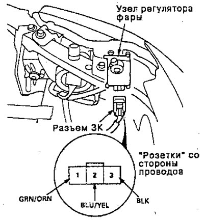
2. Check the continuity between pin No. 3 and the housing. There must be conductivity.
If there is no continuity, check:
- There is a break in the BLK wire.
- Poor grounding (G551, G552).
- If there is conductivity, go to step 3.
3. Measure the voltage between pin No. 1 and the housing with the ignition switch ON (II). There should be battery voltage.
- If there is no voltage, check for an open in the GRN/ORN wire.
- If there is battery voltage, go to step 4.
4. Using an ohmmeter, measure the resistance between terminal No. 2 and the housing at the headlight control switch position on "0". The resistance should be approximately 480 ohms.
- If resistance is not within specification, check:
- Break in BLU/YEL wire
- The headlight control switch is faulty.
- If the resistance is within specification, proceed to step 5.
5. If all tests are positive, but the headlight control unit does not work, check to see if the headlight control assembly may be frozen, stuck, or improperly installed. If the mechanical tests are positive, replace the headlight control assembly.
6. After installation, check the system again.
Checking the headlight control switch
1. Carefully pull the switch out of the rear console.
2. Disconnect the 5K connector from the switch.
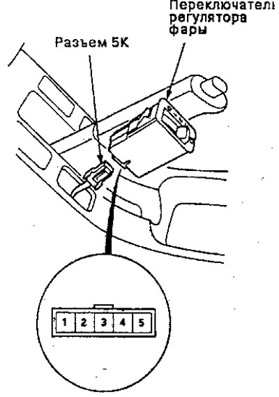
3. Measure the resistance between pins No. 1 and No. 3 and then measure the resistance between pins No. 3 and No. 5 at positions 0,1,2,3 by turning the knob.
Between No. 1 and No. 3 approximately 4.7 kOhm
Between No. 3 and No. 5:
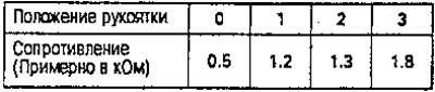
4. Replace the switch if the resistance is not within specification.