
Contents: Disassembly - five-speed gearbox ⇊ Intermediate shaft repair (4- and…⇊ Assembly ⇊ Inspection of parts ⇊ Repair of the main gear and…⇊ Assembly - five-speed gearbox ⇊ Four-speed gearbox ⇊
Disassembly - five-speed gearbox
1. Remove the box (see Part 5). Drain the oil if you haven't done so already. Wash the box.
2. Loosen the bolts and remove the rear cover from the gearbox housing (see fig. 6.2).
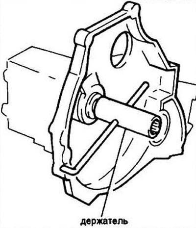
Fig. 6.2 Assembly of a 5-speed gearbox
3. Remove the retaining ring and disc washer or oil flinger (on later models).
4. Remove the secondary shaft bearing.
5. Remove the retainer (pin) of the 5th gear engagement fork.
6. Lower the 5th gear synchronizer sleeve until the gear locks.
7. Pull out the shift fork together with the 5th gear synchronizer sleeve.
8. Remove the 5th gear synchronizer sleeve, synchronizer to the spring.
9. Remove the 5th gear.
10. Remove the needle bearing.
11. Remove the thrust washer.
12. When removing the gear, note both sides. Also relative to the disc washer. If the fit is tight, you can use a puller
13. Unscrew the retainer plugs and remove the springs and balls. Use a magnet to remove the balls.
14. Remove the clutch cable bracket.
15. Unscrew the bolts securing the gearbox housing to the flywheel housing and remove the gearbox.
16. Remove the differential seal and remove the retaining ring from the gearbox housing.
17. Remove the retaining ring and tap lightly to remove the secondary shaft and intermediate shaft bearings.
18. Move aside the reverse intermediate gear shaft and gear.
19. Unscrew the reverse gear shift lever nut. Remove the special washer and remove the lever that holds the ball and spring. Keep in mind that this ball is larger in diameter than the other three.
20. Bend back the tabs of the lock washer on the three forks and unscrew the fork mounting bolts.
21. Remove the 5th/reverse shift shaft and latch.
22. Remove the 1st/2nd gear shift shaft, then 3rd/4th and the latches.
23. Move the 1st/2nd gear synchronizer sleeve until it engages the 2nd gear pinion and move the 1st/2nd gear engagement fork.
24. Remove the secondary shaft together with the intermediate shaft as a single unit.
25. Move the shift lever to gain access to the shift lever retainer bolt.
26. Remove the differential/final drive assembly from the flywheel housing.
27. Remove the differential seal.
28. Remove the dust cover and oil seal of the gearshift lever.
29. Loosen the speedometer drive holder bolts and remove the drive.
30. Using an impact screwdriver, loosen the intermediate shaft bearing holder mounting screws.
31. Remove the intermediate shaft bearing from the flywheel housing.
32. Remove the oil deflector washer.
33. Remove the breather assembly from the flywheel housing.
34. Remove the secondary shaft bearing and oil seal from the flywheel housing of the four-speed gearbox.
35. Remove the box from the car (see Section 5). Drain the oil if it has not been drained yet, wash the box.
36. Unscrew the bolts securing the rear cover from the box body (see fig. 6.2).
37. Remove the retaining ring and disc washer (to early models) or oil deflector (on later models) and the sides of the back cover.
38. Pull the bearing off the intermediate shaft.
39. Release the limiter and unscrew the intermediate shaft mounting nut. To prevent the intermediate shaft from rotating, hold the secondary shaft with a special holder or a gas wrench. Do not forget to put a rag under the jaws of the wrench so as not to damage the splines.
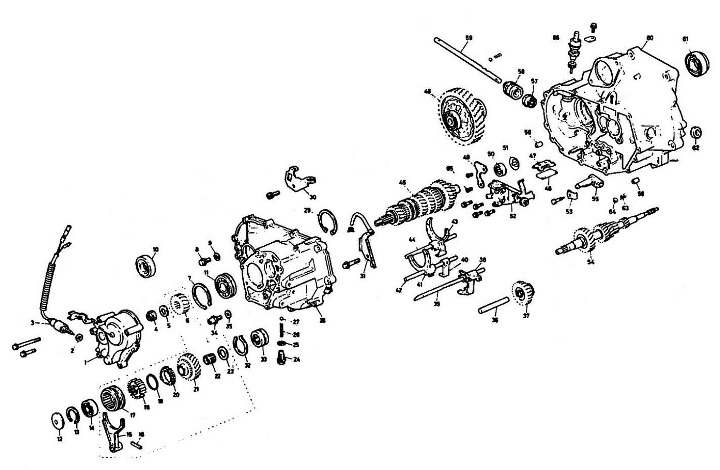
Fig. 6.39 Installing the secondary shaft holder 1 - back cover; 2 - washer; 3 - Reverse light switch; 4 - lock nut; 5 - plate washer; 6 - 5th gear pinion (leading); 7 - retaining ring; 8 - cork; 9 - washer; 10 - differential seal; 11 - intermediate shaft bearing; 12 - oil deflector washer; 13 - stopper; 14 - secondary shaft bearing; 15 - 5th gear engagement fork; 16 - finger; 17 - 5th gear synchronizer fork; 18 - 5th gear synchronizer hub; 19 - synchronizer spring; 20 - synchronizer; 21 - 5th gear pinion (driven); 22 - needle bearing; 23 - thrust washer; 24 - retainer plug; 25 - washer; 26 - retainer spring; 27 - retainer ball; 28 - box body; 29 - stopper; 30 - clutch cable bracket; 31 - breather; 32 - stopper; 33 - secondary shaft bearing; 34 - drain plug; 35 - sealing washer; 36 - reverse intermediate gear shaft; 37 - reverse intermediate gear; 38 - 5th/reverse gear engagement fork latch; 39 - latch shaft; 40 - 3rd/4th gear fork latch; 41 - 3rd/4th gear shift fork; 42 - fork shaft; 43 - 1st/2nd gear fork latch; 44 - fork shaft; 45 - intermediate shaft; 46 - differential; 47 - magnet holder; 48 - magnet; 49 - bearing support plate; 50 - intermediate shaft bearing; 51 - oil deflector washer; 52 - Shift lever holder; 53 - lock washer; 54 - secondary shaft; 55 - switch; 56 - bushing; 57 - shift shaft seal; 58 - boot; 59 - switch shaft; 60 - flywheel housing; 61 - differential seal; 62 - boot; 63 - retainer spring; 64 - retainer ball; 65 - screw; 66 - speedometer drive gear.
40. The remaining steps are identical to those described in paragraphs 13 through 34 in the section on removing the 5-speed gearbox.
Intermediate shaft repair (4- and 5-speed gearboxes)
41. Remove the spacer with the flange.
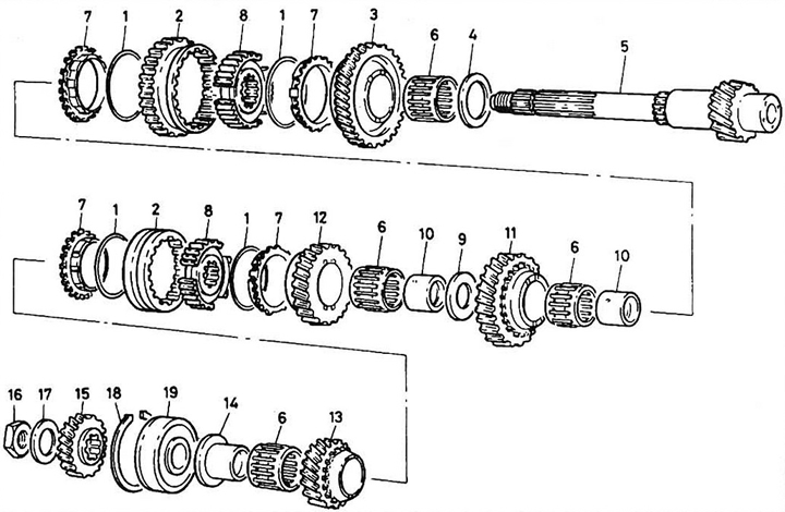
Fig. 6.41 Assembling the intermediate shaft 1 - synchronizer spring; 2 - synchronizer clutch; 3 - 1st gear pinion; 4 - 1st gear thrust washer (32 mm); 5 - intermediate shaft; 6 - needle bearing; 7 - synchronizer; 8 - synchronizer sleeve; 9 - washer; 10 - spacer 28 mm; 11 - 2nd gear pinion; 12 - 3rd gear pinion; 13 - 4th gear pinion; 14 - spacer with flange; 15 - 5th gear pinion; 16 - lock nut; 17 - disc washer; 18 - retaining ring (65 mm); 19 - bearing.
42. Remove the fourth gear.
43. Remove the synchronizer.
44. Remove the 4th gear needle bearing.
45. Remove the 3rd/4th gear synchronizer.
46. Remove the 3rd gear synchronizer spring.
47. Remove the third gear gear.
48. Remove the needle bearing and spacer.
49. Remove the washer and second gear.
50. Remove the synchronizer ring and 1st/2nd gear spring.
51. Remove the needle bearing and spacer.
52. Remove the 1st/2nd gear synchronizer unit. The synchronizer sleeve is made together with the reverse gear.
53. Remove the 1st gear synchronizer gear, ring and spring.
54. Remove the needle bearing and thrust washer.
55. Wash and inspect the parts. Replace them if necessary. Lightly lubricate all parts with oil.
Assembly
56. Install the thrust washer and needle bearing.
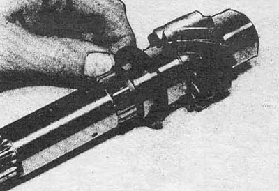
Fig. 6.56a Install the thrust washer on the intermediate shaft...
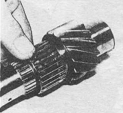
Fig. 6.56b... and needle bearing
57. Install the first gear pinion and synchronizer.
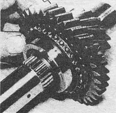
Fig. 6.57a Install the 1st gear pinion
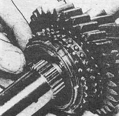
Fig. 6.57b...and synchronizer
58. Install the 1st/2nd gear synchronizer unit (together with the reverse gear), synchronizer and spring, spacer and needle bearing of 2nd gear.
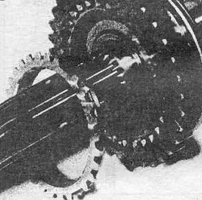
Fig. 6.58a Install the 1st/2nd gear synchronizer unit and spring
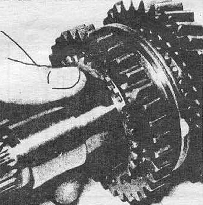
Fig. 6.586...spacer...
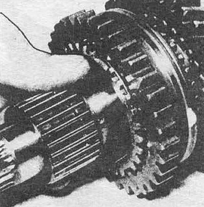
Fig. 6.58c... needle bearing
59. Install the second gear pinion.
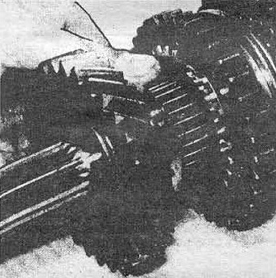
Fig. 6.59 Installing the second gear pinion
60. Install the washer.
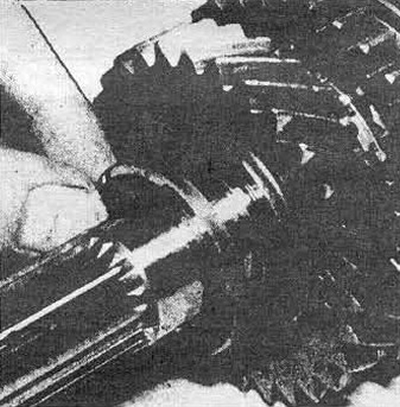
Fig. 6.60 Installing the washer
61. Install the spacer and needle bearing.
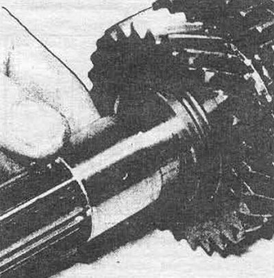
Fig. 6.61a Installing the 3rd gear spacer
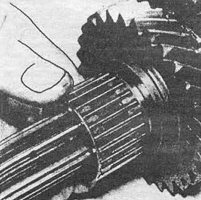
Fig. 6.61b... and needle bearing
62. Install the third gear gear.
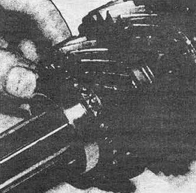
Fig. 6.62 Installing the third gear pinion
63. Install the synchronizer and spring.
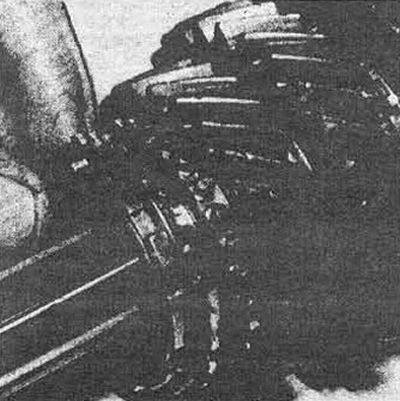
Fig. 6.63 Installing the synchronizer and spring
64. Install the 3rd/4th gear synchronizer unit.
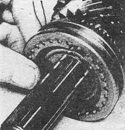
Fig. 6.64 Installing the 3rd/4th gear synchronizer unit
65. Install the needle bearing.
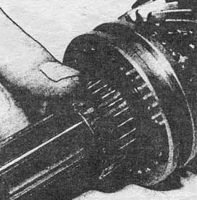
Fig. 6.65 Installing the needle bearing
66. Install the spring, synchronizer and 4th gear.
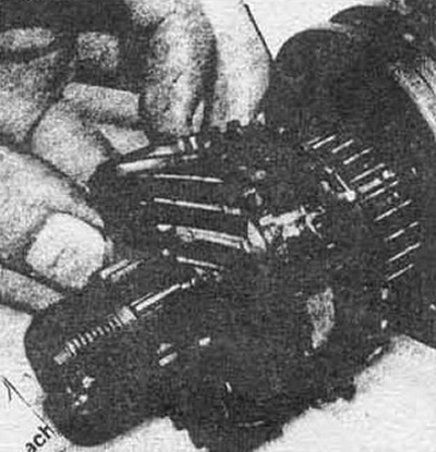
Fig. 6.66 Installing the spring, synchronizer and fourth gear
67. Install the spacer with flange.
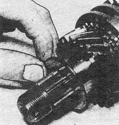
Fig. 6.67 Installing a spacer with a flange
68. Lightly tighten the flange spacer and measure the end play in each gear. If any measurement is outside specification, replace the appropriate adjuster link as necessary (washers and spacers).
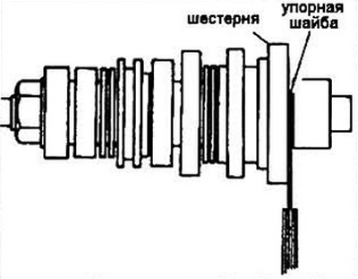
Fig. 6.68a Measuring the axial clearance of the 1st gear
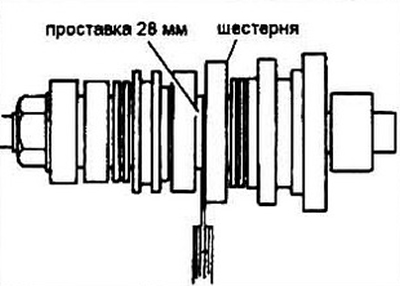
Fig. 6.686 Measuring the axial clearance of the 2nd gear
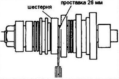
Fig. 6.68c Measuring the axial clearance of the 3rd gear pinion
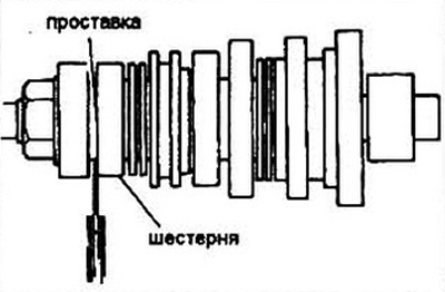
Fig. 6.68g Measuring the axial clearance of the 4th gear
69. If you are assembling a 5-speed gearbox, install the 5th gear pinion thrust washer on the secondary shaft, then the pinion itself, the needle bearing and the synchronizer unit. Lightly tighten the synchronizer sleeve and check the axial clearance in the pinion. If the axial clearance is outside the permissible limits, replace the thrust washer.
Inspection of parts
70. Inspect the gearbox housing and flywheel housing for cracks, especially in the bolt hole areas. Clean the magnetic trap.
71. Inspect the shafts for grooves, scoring, wear and chipped gear teeth.
72. Check the bearings. They should rotate smoothly and without rattling sounds. Always replace the bearings installed in the flywheel housing if they have been removed.
73. Check the gap in the synchronizer fork/clutch pair. If the gap is greater than the permissible (given in the specification) - replace the fork.
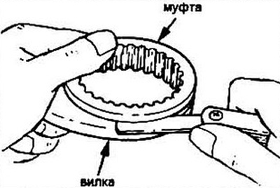
Fig. 6.73 Measuring the gap in the synchronizer fork/clutch pair
74. Press the synchronizer and engage it with the gear. Check by twisting it for any gap in the engagement - it should be minimal or completely absent (see specification data). Otherwise, replace the synchronizer.
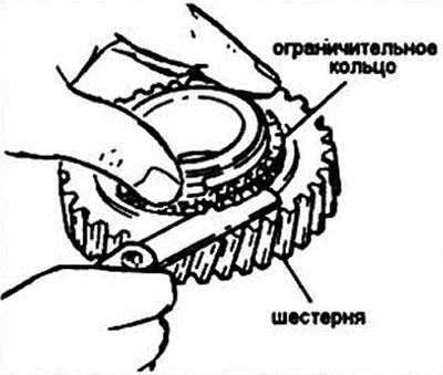
Fig. 6.74 Checking the gap in the synchro-igniter/shutter pair
75. Wear of the synchronizer unit with warranty provides noise during switching. Replace the worn synchronizer unit.
76. If you have disassembled the synchronizer unit, please note that the hub can only be installed in the coupling in one of three positions determined by the main splines. Therefore, mark the relative position of the hub and sleeve before disassembling.
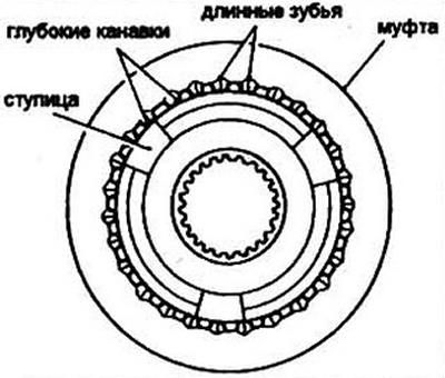
Fig. 6.76 Installing the synchronizer hub into its coupling
77. To disassemble the intermediate shaft, refer to steps 41-54. The secondary shaft is made as a single unit and cannot be disassembled: if it is unusable, it is replaced as a whole.
78. When assembling, use new seals and gaskets. The same applies to the intermediate shaft mounting nut.
Repair of the main gear and differential
79. To gain access to the differential, follow steps 1-40.
80. The differential and final drive usually do not break, however, it would be a good idea to inspect the integrity of the teeth on the gears and the side clearance.
81. Before disassembling the main gear/differential unit, mark the position of the main gear driven gear relative to the differential, and unscrew the driven gear mounting bolts. Note: the bolts have left-hand threads.
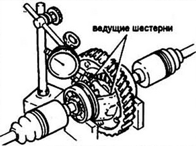
Fig. 6.81. Assembly of the differential/main gear unit 1 - clutch housing; 2 - oil seal; 3 - bearing; 4 - driven gear of the main transmission; 5 - pin; 7 - drive gear shaft; 8 - leading gear; 9 - thrust washer; 10 - bearing; 11 - side gear; 12 - oil seal; 13 - box body; 14 - stopper; 15 - differential assembly.
82. Remove the pin from the drive gear shaft.
83. Using light tapping, remove the shaft from the differential housing.
84. Remove the drive gears, thrust washers and side gears.
85. Using a suitable puller, remove the differential bearings.
86. Assembly is carried out in the reverse order. Only the inner bearing rings are pressed in.
87. When installing the driven gear of the main transmission, position the recess on the flange towards the differential according to the previously applied marks. Adjustment relative to the position of the main transmission gears is carried out using adjusting washers.
88. To adjust the clearance in the main gear drive gears, connect the drive axles. Place the differential cup in a V-shaped stand and measure the clearances in the drive gears with an indicator head. If the clearance is outside the permissible limits, (see specification), replace the thrust washers.
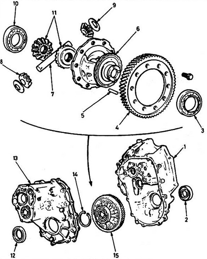
Fig. 6.88 Measuring clearances in the main gear drive pinions. Connect the drive axles
Assembly - five-speed gearbox
89. Install the secondary shaft bearing and seal into the flywheel housing.
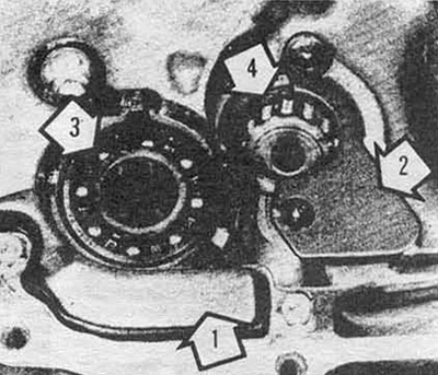
Fig. 6.89 Flywheel housing assembly: 1 - breather; 2 - bearing holder; 3 - secondary shaft bearing; 4 - intermediate shaft bearing
90. Install the breather on the flywheel housing.
91. Install the oil deflector ring.
92. Install the intermediate shaft bearing and bearing holder into the flywheel housing and tighten the holder mounting screws.
93. Install the speedometer drive shaft and secure it.
94. Install the shift shaft seal and boot.
95. If the differential bearings were replaced, push them slightly into the transmission housing until the retaining rings are seated, then install the differential into the flywheel housing.
96. Connect the flywheel housing and the gearbox housing and check the clearance between the retaining ring and the outer ring of the differential bearing. If the clearance is outside the permissible limits, (see specification), install a retaining ring of a different thickness (see specification).
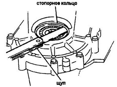
Fig. 6.96 Checking the clearance between the outer ring of the bearing and the retaining ring
97. Remove the gearbox housing and install the differential into the flywheel housing.
98. Insert the spring and the ball of the shift lever retainer into the hole in the flywheel housing.
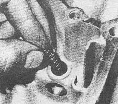
Fig. 6.98a Install the engagement shaft retainer spring, then the ball
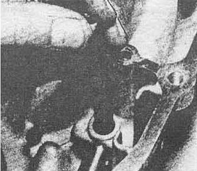
Fig. 6.98b...press on the ball...
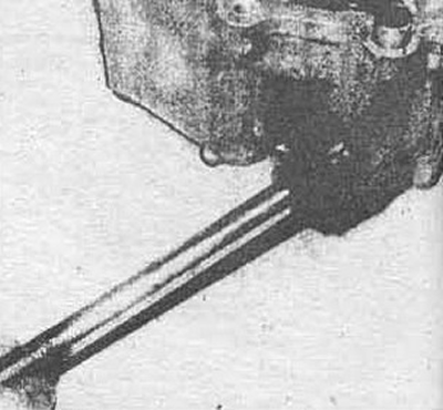
Fig. 6.98c...and insert the shift shaft into the flywheel housing
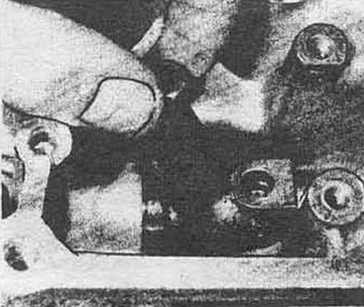
Fig. 6.98g. Install the shift lever on the inner end of the shaft...
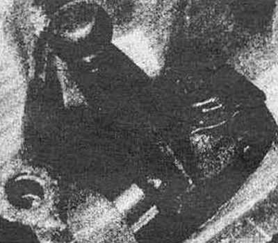
Fig. 6.98d...push the shaft until it fits into the opposite boss. Tighten the bolt and secure it
99. Check the correct orientation of the shift lever and install the lever holder. Tighten the holder bolts to the torque specified in the specification.
100. Simultaneously install the secondary and intermediate gears, aligning their corresponding gears, into the flywheel housing.
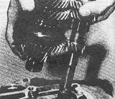
Fig. 6.100a. Align the secondary and intermediate shaft gears...
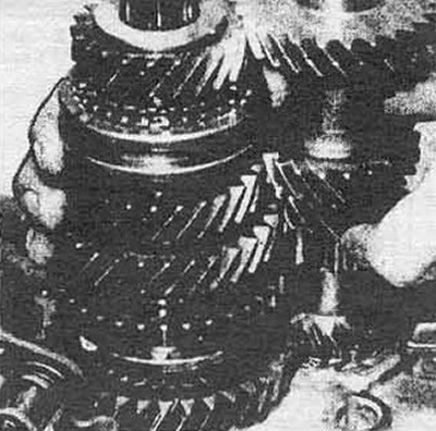
Fig. 6.100b... and install them in the flywheel housing
101. Slide the 1st/2nd gear synchronizer sliding sleeve until it engages with the 2nd gear gear and install the shift fork into the sleeve groove.
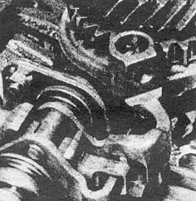
Fig. 6.101. Move the 1st/2nd gear synchronizer sleeve until it engages with the 2nd gear pinion and insert the engagement fork into the sleeve groove
102. Install the 3rd/4th gear shift shaft and fork.
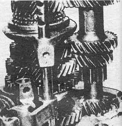
Fig. 6.102. Installing the 3rd/4th gear shift shaft and shift fork
103. Install the 1st/2nd gear selector shaft.
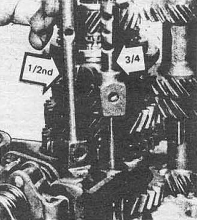
Fig. 6.103. Installing the 1st/2nd gear engagement shaft
104. Orient the 5th/reverse gear engagement latch and insert the engagement shaft through it.
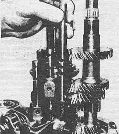
Fig. 6.104. Orient the 5th/reverse gear engagement latch and insert the engagement shaft through it
105. Make sure that the grooves of the locking pins on the engagement shafts enter the flywheel housing and are positioned towards the gearbox housing.
106. Tighten the bolts securing the gear shift forks, placing new lock washers under the bolts. Bend back the lock tab of the washer.
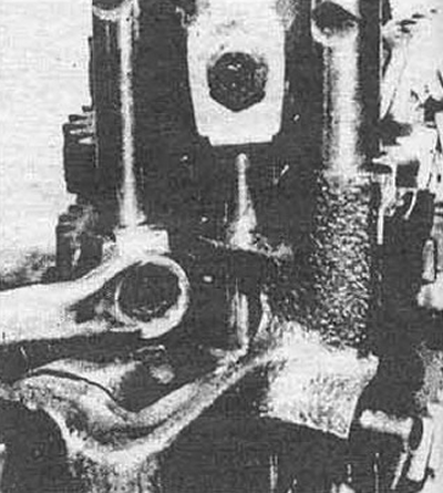
Fig. 6.106. Tighten the fork mounting bolts on the shafts. Use only new lock washers. Firmly press the tongue of the new lock washer against the edge of the bolt
107. Install the reverse lock spring and ball, gear engagement lever, special washer and nut.
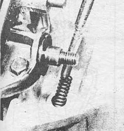
Fig. 6.107a. Install the reverse lock spring, then the lock ball
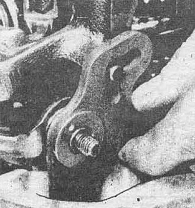
Fig. 6.107b. Install the reverse gear lever, orient it correctly relative to the ball...
108. Install the reverse idler gear and shaft.
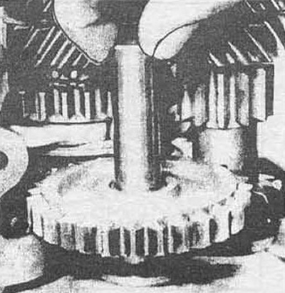
Fig. 6.108. Installing the shaft and reverse intermediate gear
109. Install the secondary and intermediate shaft bearings, having loosened the retaining rings, into the gearbox housing.
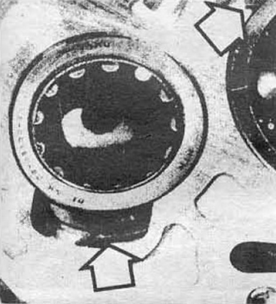
Fig. 6.109. Release the retaining rings and insert the secondary and intermediate shaft bearings
110. Make sure the guide pins are in place in the box body. Apply sealing paste to the mating surface. Install the magnet.
111. Lightly lubricate the ends of the shafts and the differential bearings to facilitate assembly of the gearbox housing and flywheel housing.
112. Pair the gearbox housing and flywheel housing, install the bolts and tighten them to the torque specified in the specification, in the sequence shown in Fig. 6.112 a, b.
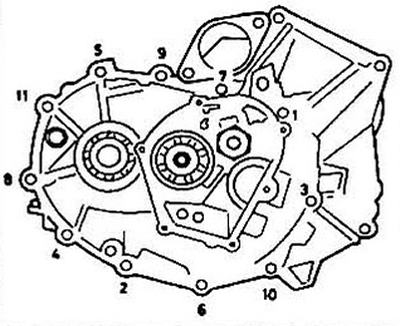
Fig. 6.112. Tightening order of the bolts securing the gearbox to the crankcase
113. Install the breather hose and clutch cable bracket.
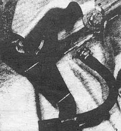
Fig. 6.113. Installing the breather hose and clutch cable bracket
114. Install the balls, springs and retainer plugs.
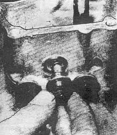
Fig. 6.114. Install the retainer ball, then the spring and tighten the plug
115. Install the 5th gear gear on the intermediate shaft with the boss towards the bearing.
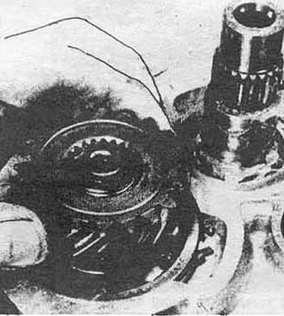
Fig. 6.115. Installing the 5th gear pinion
116. Install the disc washer with the recess towards the gear.
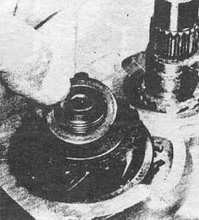
Fig. 6.116. Install the disc washer with the groove towards the gear
117. Install the fifth gear synchronizer hub onto the secondary shaft. Using a depth gauge, measure height A. Take the average of three measurements around the bearing circumference.
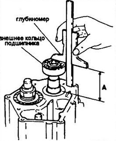
Fig. 6.117. Measuring the bearing height (dimension A is equal to the height of the rear cover)
118. Remove the bearing and synchronizer hub from the secondary shaft. If you can no longer do this, remove the snap ring, disc washer or oil flinger from the rear cover.
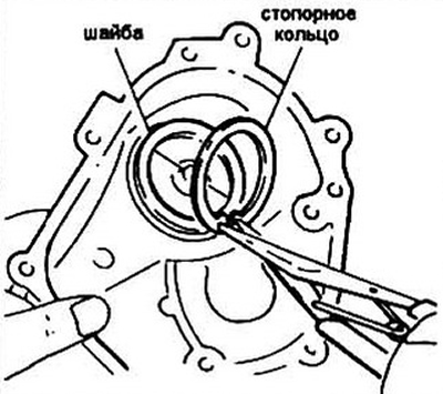
Fig. 6. 118a. Remove the stopper and disc washer from the rear cover (early models)
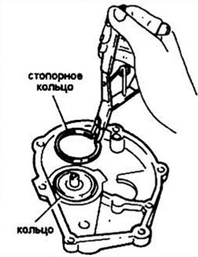
Fig. 6.118b. Remove the stopper and oil-deflecting ring (late models)
119. Place a rigid ruler along the cover flange and measure the distance B using a depth gauge. Take the average of three measurements at equidistant points on the retaining ring seat and subtract the thickness of the ruler.
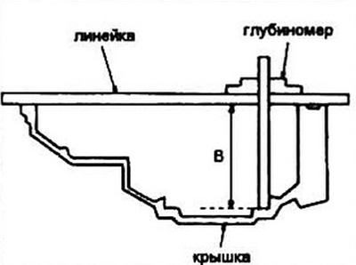
Fig. 6.119. Place a rigid ruler along the rear cover flange and measure the distance B
120. To calculate the thickness of the fifth gear retaining ring, use the following formula.
- On early models: B - A - 0.85 = thickness of the retaining ring.
- On later models with oil flinger ring: B - A - 0.11... 0.18 = thickness of retaining ring.
121. Install the disc washer or oil flinger ring into the rear cover of the box, then install the stopper.
122. Install the 5th gear thrust washer, needle bearing and gear onto the secondary shaft.
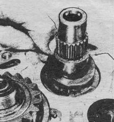
Fig. 6.122a. Install the 5th gear thrust washer...
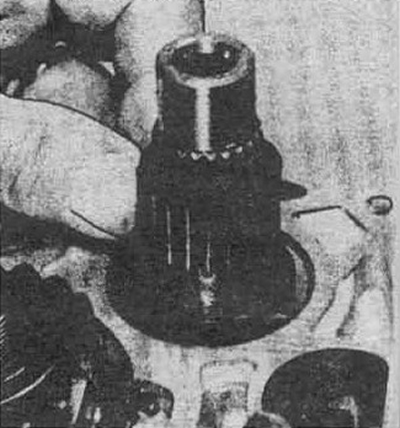
Fig. 6.122b... needle bearing
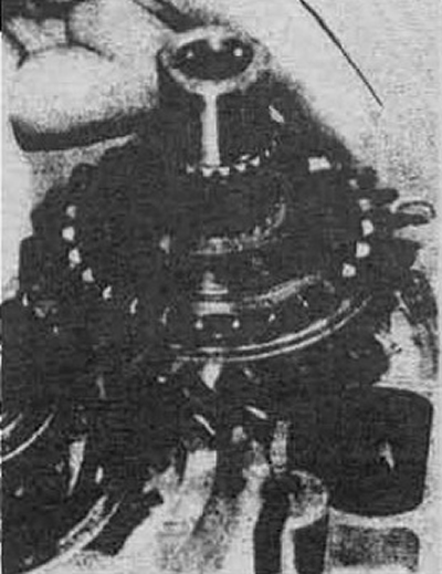
Fig. 6.122b... and the gear on the secondary shaft
123. Install the synchronizer and spring.
124. Install the synchronizer hub with the recess towards the gear
125. Engage the 5th gear fork with the groove of the synchronizer clutch (the recess is directed towards the gear) and install the fork and the coupling as a single unit on the shaft. Remember that the coupling can only be installed on the hub with one side in one of the three positions of the main splines. Lower the synchronizer coupling down.
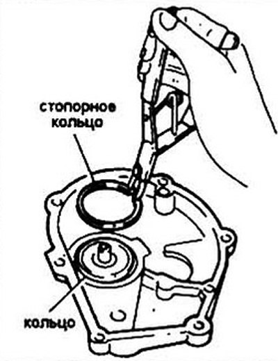
Fig. 6.125. Install the fifth gear engagement fork into the groove of the synchronizer clutch and install them as one unit
126. Take a new intermediate shaft nut and tighten it to the specified torque. Loosen the nut and tighten it again to the same torque. Lock the nut (see fig. 6.126).
127. Install the locking pin into the 5th gear engagement fork.
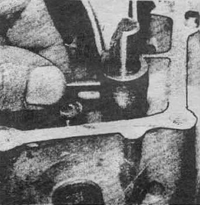
Fig. 6.127. Insert the locking pin into the 5th gear fork
128. Install the secondary shaft bearing. The number engraved on the bearing ring should face you.
129. Apply sealing paste to the bearing surface, make sure the guide pins are in the rear cover and install the cover. Tighten the bolts.
130. Install the reversing lamp switch.
131. Check that all gears are engaged.
132. Install the clutch release bearing (if it was filmed).
Four-speed gearbox
133. Perform operations according to steps 89-114.
134. Install the secondary shaft bearing and measure the height A. Take the average of three measurements around the bearing circumference.
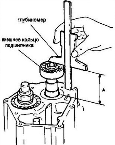
Fig. 6.134. Measuring the secondary shaft bearing seat height (dimension A)
135. Remove the bearing from the secondary shaft. Remove the retainer and remove the disc washer or oil deflector ring from the rear cover if you have not done so already.
136. Calculate the required thickness of the retaining ring using the formulas described in steps 119-121.
137. Secure the intermediate shaft from turning and screw in a new lock nut. Tighten it to the torque specified in the specification, release it and tighten it again. Lock the nut.
138. Apply sealing paste, make sure the guide pins are present and secure the back cover.
139. Install the reversing lamp switch.
140. Check that the gears are engaged correctly.
141. Install the clutch release bearing (if it was dismantled).
[The article is based on information from the website «HONDABOOK»]