
Note: If the engine has been overheated, there is a high chance of warping the head (see step 12).
Cleaning
2. Remove all traces of old gasket and seals from all mating surfaces. Do not scratch surfaces.
3. Clean all coolant passages.
4. Use a stiff brush to clear all holes of deposits.
5. Using taps, clean all threaded holes from corrosion and contamination. Blow holes with compressed air.
6. Wash the head with solvent and dry it.
7. Rinse and blow out the rocker arms with compressed air (try not to confuse them).
8. Wash and dry valve springs, spring seats, crackers and plates. Do not mix parts belonging to different valves.
9. Clean the valves from carbon deposits.
Inspection
Cylinder head
10. Inspect the head for cracks indicating coolant leaks and other damage. If cracks are found and cannot be repaired, replace the head.
11. Using a parallel bar and flat feeler gauges, measure head warp. If warping exceeds the limit, the head requires machining.
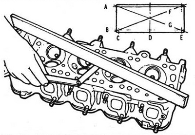
Pic. 9.11 Checking head warp with a parallel bar and feeler gauge
12. Examine the condition of the valve seats in each combustion chamber. If they are worn, cracked or burnt out, they need to be repaired.
13. Measure valve stem/guide clearance by jiggling the valve and dial gauge. In this case, the deviation of the valve from the seat should be about 1.5 mm. The total indication of the indicator when the rod is rocking must be divided by two to obtain the actual gap value. If the measurement results are in doubt, re-measure in a different way.
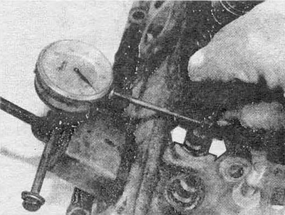
Pic. 9.13 Measuring the gap in the guide using an indicator. The arrows show the direction of stem swaying
Valves
14. Carefully inspect the valve face for wear, distortion, pitting, and burnouts. Inspect the stem: is there any scuffs, nicks or cracks on it, determine the presence of curvatures by rotating the valve. There should be no excessive wear or pitting at the end of the stem. The presence of any of the listed defects indicates the need to restore the valve.
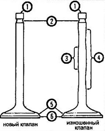
Pic. 9.14 Places for measuring valve stem wear:
1 - stem end;
2 - cracker grooves;
3 - zone of least wear;
4 - zone of greatest wear;
5 - chamfer of the valve;
6 - plate.
15. Measure the thickness of the edge of the valve disc. If the edge thickness is less than the limit, the valve must be replaced.
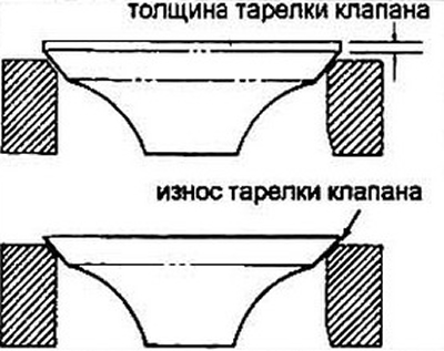
Pic. 9.15 The thickness of the valve disc should not be less than given in the specification. Otherwise, the valve must be replaced
Valve parts
16. Check valve springs for wear and pitting. Measure the free length of the spring and compare it with the limit. Springs that are shorter than the permitted length must not be reinstalled. In addition to measuring the free length, the springs must be culled according to the stiffness value (work on special equipment).
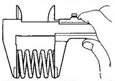
Pic. 9.16 Measuring the free length of a spring
17. Install the spring on a flat surface and check its perpendicularity. If the spring is bent, replace it.
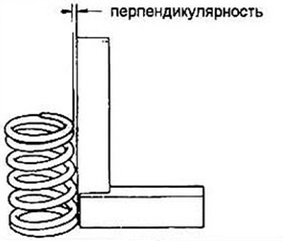
Pic. 9.17 Measuring the perpendicularity of the ends and the axis of the spring
18. Inspect the plates and crackers. If there is any doubt about the suitability of these parts, replace them.
Rocker arms
19. Check rocker arm contact surfaces for pitting, wear, nicks, chips, and unevenness. Check the condition of the threads of the adjusting screws. Inspect each rocker arm for cracks.
20. Check up a condition of carving openings of bolts of racks of axes of yokes.
All details
21. Any damaged or worn parts must be replaced with new ones.
22. If the result of the inspection fixes the general poor condition of the valve mechanism, and the wear of its parts turned out to be beyond the permissible range, which caused the engine to be repaired, refer to paragraph 10 for recommendations.