
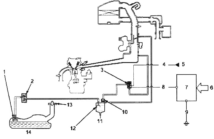
1. EVAP VALVE IN FUEL TANK
2. EVAP TWO-WAY VALVE
3. EVAP PURGE SOLENOID VALVE
4. BLACK-YELLOW WIRE
5. IGNITION COIL FUSE (15 A)
6. VARIOUS SENSORS
7. ECM/PCM MODULE
8. RED WIRE
9. BLACK WIRE
10. EVAP PURGE VALVE
11. FRESH AIR
12. EVAP CARBON FILTER
13. FUEL TANK FILLER CAP
14. FUEL TANK
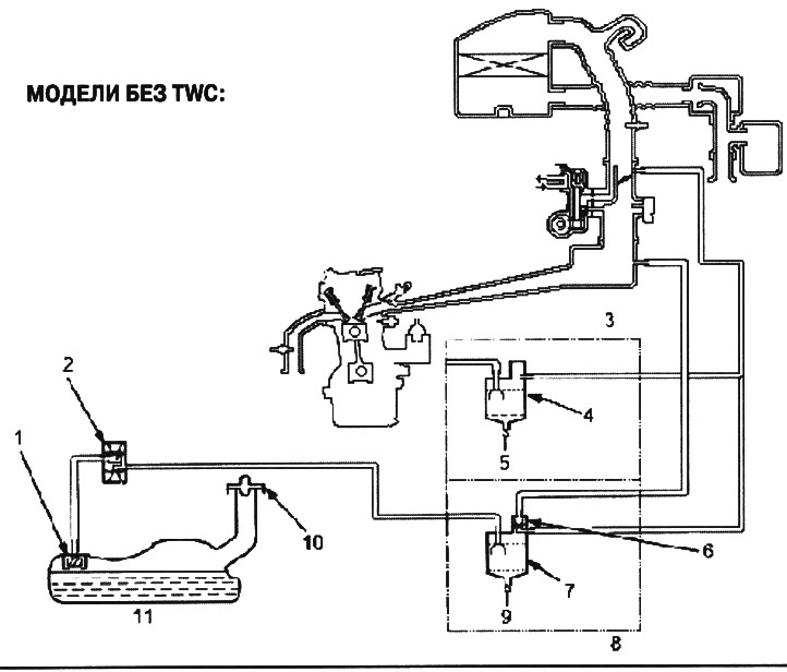
1. EVAP VALVE IN FUEL TANK
2. EVAP TWO-WAY VALVE
3. (without RSU)
4. EVAP CARBON FILTER
5. FRESH AIR
6. EVAP PURGE VALVE
7. EVAP CARBON FILTER
8. (with PCV)
9. FRESH AIR
10. FUEL TANK FILLER CAP
11. FUEL TANK
Description
The fuel vapor recovery system serves to reduce the emission of fuel vapors into the atmosphere. The system consists of the following components:
A. Evaporative emission (EVAP) canister. The EVAP canister is used to temporarily store fuel vapor until it can be purged from the canister into the engine and burned.
B. Vapor Purge Control System. EVAP canister purge is accomplished by drawing fresh air through the EVAP canister and into the throttle body passage. Purge vacuum is controlled by the EVAP purge diaphragm valve and the EVAP purge solenoid valve (on TWC models).
C. Fuel tank vapor regulation system. When the fuel vapor pressure in the fuel tank is higher than the EVAP two-way valve setting, the valve opens and regulates the flow of fuel vapor to the EVAP canister.
Check (models without TWC)
1. Remove the fuel tank filler cap.
2. Start the engine and let it run at idle speed.
3. Disconnect the EVAP purge valve diaphragm vacuum hose (on the EVAP canister) and connect a vacuum gauge to the hose.
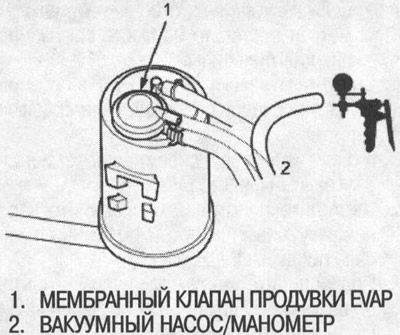
If there is no vacuum, check the vacuum hose for blockages, cracks, or disconnections, and the vacuum passage for blockages.
4. Disconnect the vacuum gauge and connect the vacuum hose.
5. Connect a vacuum gauge to the EVAP canister purge air hose.
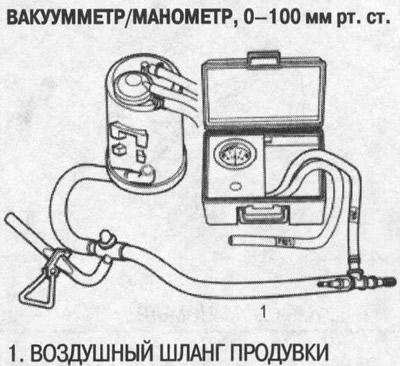
6. Increase the engine speed to 3500 rpm. After 1 minute, the device should show a vacuum.
- If the vacuum is registered by the device after 1 minute, remove the device, the test is complete.
- If there is no vacuum, disconnect the vacuum gauge and replace the filler cap.
7. Remove the EVAP carbon canister and inspect for any signs of damage or defects.
- If damaged, replace the EVAP canister.
8. Stop the engine. Disconnect the upper vacuum hose from the EVAP purge valve.
Connect the vacuum pump to the lower vacuum hose as shown in the figure and create a vacuum.
The vacuum must remain constant.
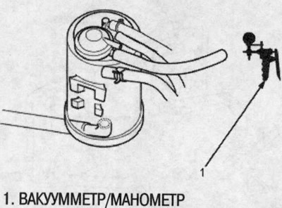
If the vacuum drops, replace the EVAP canister and retest.
9. Restart the engine. Reconnect the upper vacuum hose to the EVAP purge valve.
The vacuum (from the lower vacuum hose side) should drop to zero.
If the vacuum does not drop to zero, replace the EVAP canister and retest.
Checking the EVAP 2-Way Valve
1. Remove the fuel tank filler cap.
2. Disconnect the vapor bleed tube from the two-way valve on the fuel tank and connect it to the tee from the vacuum gauge and vacuum pump as shown in the figure.
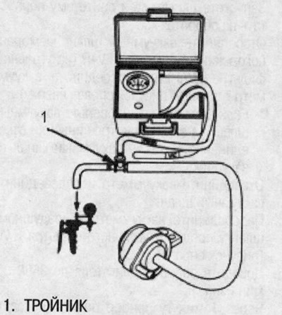
3. Slowly create a vacuum and continuously monitor the instrument readings.
The vacuum should immediately stabilize at 0.7-2.0 kPa (5-15 mmHg).
If the vacuum stabilizes (valve opens) at below 0.7 kPa (5 mmHg) or above 2.0 kPa (15 mmHg), install a new valve and retest.
4. Move the vacuum pump hose from the vacuum connection to the pressure connection, and the vacuum gauge hose from the vacuum side to the pressure side, as shown in the figure.
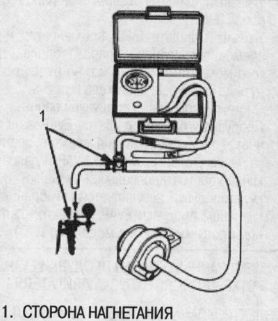
5. Slowly build up pressure in the vapor discharge tube while observing the instrument readings.
The pressure should stabilize at 1.3-4.7 kPa (10-35 mmHg).
- If the pressure immediately stabilizes (the valve opens) at 1.3-4.7 kPa (10-35 mmHg), the valve is OK.
- If the pressure stabilizes below 1.3 kPa (10 mmHg) or above 4.7 kPa (35 mmHg), install a new valve and retest.
(You will find the original on the portal: HondaBook.ru)