
General information
The system accumulates fuel vapors that accumulate in the fuel system while the vehicle is parked and ensures that they are discharged into the intake manifold for combustion during normal engine operation.
Any EVAP system necessarily includes a special adsorber filled with activated carbon, which actually collects fuel vapors. The method of removing vapors from the adsorber may vary depending on the design of a specific system. The description below will allow the reader to understand in sufficient detail the operating principles of any type of EVAP system.
Note: The design described does not necessarily have to be exactly the same as the system installed on a specific vehicle, but the operating principle is common to all models equipped with a fuel injection system. If any deviations are found, check the information on the VECI label located under the hood.
The fuel filler cap is equipped with a two-way safety valve. In the event of a system failure, the valve ensures the removal of fuel vapors into the atmosphere.
Another shut-off valve (ORVR valve) is installed near the fuel tank and regulates the removal of fuel vapors into the carbon adsorber depending on the pressure/vacuum differences associated with temperature changes.
On the way to the carbon adsorber, fuel vapors pass through a two-way valve and through ventilation hoses enter the carbon adsorber installed in the engine compartment, where they accumulate during the entire parking period.
When the engine is started, the purge solenoid valve of the adsorber remains closed until it warms up to a certain temperature, allowing the purge diaphragm valve to open due to the increase in the depth of vacuum in the intake manifold. From the adsorber, fuel vapors are blown out through the diaphragm valve into the intake manifold, from where they enter the combustion chambers, where they are burned out during normal engine operation.
The fuel tank is also equipped with a sensor that monitors changes in pressure in the tank both when the vehicle is parked and while driving.
Examination
Note: A complete inspection of the EVAP system is beyond the skill level of the average DIY mechanic. Fortunately, the EVAP system, like other emission control systems, is protected by additional warranties. Most EVAP system failures are due to a damaged canister or failed vacuum hoses.
1. Always check the condition of the vacuum hoses first, as damage or disconnection of the hoses is most often the cause of system failure (check the hose routing diagram on the VECI label of your vehicle). Replace damaged hoses if necessary.
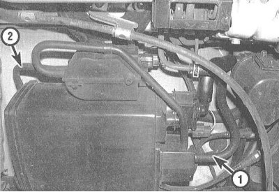
2. Disconnect the vacuum line from the carbon canister and connect a vacuum gauge to the hose. When the engine is cold (below 66°C) and idling, there should be no vacuum here - otherwise, check the condition of the canister purge control solenoid valve. If there is no vacuum, increase the engine speed to 3000 rpm and warm up the unit to normal operating temperature (the cooling fan should operate). Now the device should register a vacuum - otherwise, again check the condition of the purge control valve (see paragraph 7).
3. Disconnect the vacuum hose from the EVAP two-way valve (near the charcoal canister) and connect a hand-held vacuum pump to it. Make sure the pump is directly connected to the two-way valve. With the ignition on (do not start the engine), create a vacuum and make sure the valve holds it securely. A leaking valve must be replaced.
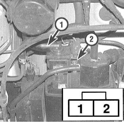
4. With the ignition on (engine not running), disconnect the charcoal canister vent shutoff valve (see accompanying illustration) and check that the two-way valve holds vacuum. If this condition is met, replace the shutoff valve together with the O-ring. Otherwise, check the wiring in the circuit section between the shutoff valve and the PCM.
5. Disconnect the vacuum hose from the charcoal canister vent shut-off valve, connect a hand vacuum pump and with the ignition on (do not start the engine), make sure that the valve does not leak, otherwise replace it.
6. Disconnect the wiring from the charcoal canister vent shut-off valve and, with the ignition on (do not start the engine), check for battery voltage between terminal No.1 of the connector and ground. If there is no voltage, check the condition of the wiring in the circuit section between the shut-off valve and fuse No.6 for 15 A.
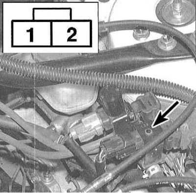
7. Disconnect the 2-pin connector of the purge control solenoid valve of the adsorber and with the ignition on (do not start the engine), make sure that there is battery voltage at terminal No.1 of the connector. If there is no power, check the wiring in the section of the circuit between the solenoid valve and fuse No.6 for 15 A.
Note: The charcoal canister purge control solenoid valve is located on the left side of the engine compartment rear bulkhead (on V6 models) or on the intake manifold (on 4-cylinder models).
8. Warm up the engine to normal operating temperature (the cooling fan should operate). Verify that vacuum returns from the purge control solenoid back to the intake manifold. If there is still no vacuum, disconnect the 2-pin electrical connector and recheck the vacuum in the manifold. If there is still no vacuum, check the condition and proper routing of the vacuum hoses. If vacuum is present, check for a short in the wiring between the 2-pin connector and the PCM.
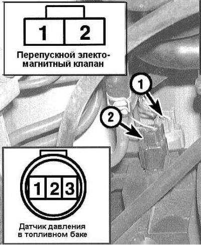
9. Disconnect the 2-pin connector at the EVAP bypass solenoid valve. With the ignition on (do not start the engine), there should be battery voltage at terminal #1. If there is no power, check the wiring between the valve and the #6 15A fuse.
10. Disconnect the 3-pin connector of the fuel tank pressure sensor wiring and with the ignition on (do not start the engine), measure the voltage between terminals No.1 and 2 of the connector. Then measure the voltage between terminals No.2 and 3. In both cases, the device should register a value of about 5 V. If the check gives a positive result, however, OBD again records a sensor malfunction, replace the sensor.
11. Check the carbon canister for signs of leaks. Remove the canister assembly and plug all of its vent lines. Connect a hand vacuum pump to the canister vent shutoff valve, create a vacuum, and check for leaks. Replace the canister if necessary.
Replacement
Carbon adsorber
1. Disconnect all ventilation hoses from the canister assembly, unscrew the bolts and remove the assembly from under the vehicle. Make sure that all disconnected hoses are properly labeled.
2. Installation is carried out in reverse order.
EVAP 2-way valve, vent shut-off valve, fuel tank pressure sensor and EVAP bypass solenoid valve
3. To gain access to the listed valves/sensors, remove the carbon canister, then remove each component individually.
4. Installation is carried out in reverse order.
Carbon adsorber purge control solenoid valve
5. Disconnect the vacuum hoses from the charcoal canister purge control solenoid valve.
6. Remove the mounting bolt and remove the valve from the engine compartment.
7. Installation is carried out in reverse order.