
2. Disconnect the negative battery terminal first, then the positive terminal.
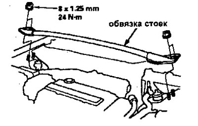
3. Remove the strut trim (engines V16A2, V16A4, V16A5, V16A6).
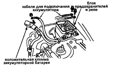
4. Disconnect the connection cables from the fuse and relay box.
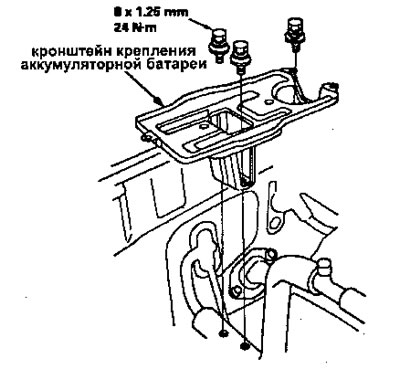
5. Remove the battery and battery mounting bracket.
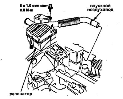
6. Remove the air intake duct and air filter housing.
Engines D14A3, D14A4, D15Z4, D15Z5, D16Y7:
1. Remove the resonator and air intake duct.
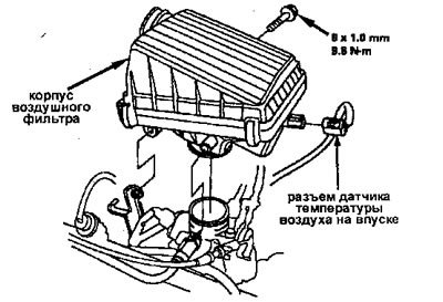
2. Disconnect the intake air temperature sensor connector, then remove the air filter housing.
In addition to engines D14A3, D14A4, D15Z4, D15Z5, D16Y7:
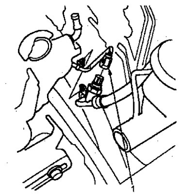
1. Disconnect the intake air temperature sensor connector, then remove the intake air duct and air filter housing.
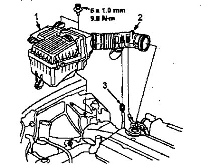
1 - air filter housing;
2 - inlet air duct;
3 - intake air temperature sensor connector.
7. Disconnect the engine wiring harness connector.
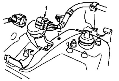
1 - engine wiring harness connector
8. Relieve fuel pressure and loosen the service bolt on the fuel filter approximately one turn.
Do not smoke when working on the fuel system. Keep open flames away from the work area. Drain the fuel into a suitable container.
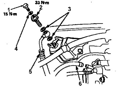
9. Remove the fuel vapor removal system hose from the intake manifold and the fuel supply hose.
Engines D14A3, D14A4, D15Z4, D15Z5, D16Y7:
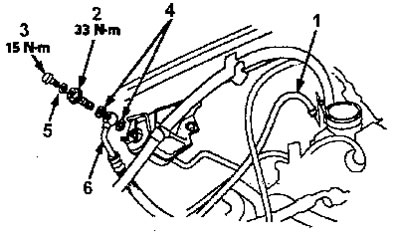
1 - hose for the fuel vapor removal system from the intake manifold;
2 - bypass bolt;
3 - technological bolt;
4 - washers;
5 - washer;
6 - fuel supply hose.
In addition to engines D14A3, D14A4, D15Z4, DD15Z5, D1GY7:
1 - technological bolt;
2 - bypass bolt;
3 - washers;
4 - washer;
5 - fuel supply hose;
6 - hose for the system for removing fuel vapors from the intake manifold.
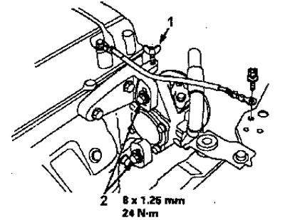
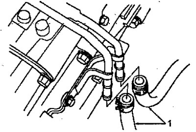
10. Remove the brake booster vacuum hose, fuel return hose and vacuum hose.
Engines D14A3, D14A4, D15Z4, D15Z5, D16Y7:
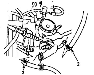
1 - vacuum hose;
2 - vacuum hose of the vacuum brake booster;
3 - fuel return hose.
In addition to engines D14A3, D14A4, D15Z4, D15Z5, D16Y7:
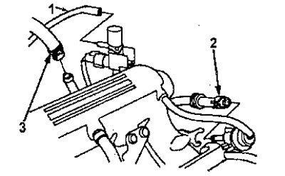
1 - vacuum hose;
2 - fuel return hose;
3 - vacuum hose of the vacuum brake booster.
11. Disconnect the ECM/PCM connectors.
12. Disconnect the main wiring harness connector.
13. Remove the insulating boot and wiring harness clamps, then remove the ECM/PCM connectors.
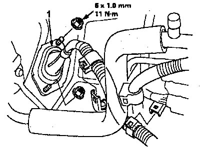
1 - insulating case.
14. Remove the power steering pump drive belt and pump.
Attention: Do not disconnect the hoses from the power steering pump.
Engines V16A2, V16A4, V16A5, V16A6:
1. Remove the adjusting bolt and mounting bolts, then remove the power steering pump drive belt and pump.
Engines V16A2, V16A4, V16A5, V16A6:
1 - adjusting bolt;
2 - fastening bolts.
In addition to engines V16A2, V16A4, V16A5, V16A6:
1. Remove the mounting bolt and fixing bolt, then remove the power steering pump drive belt and pump.
In addition to engines V16A2, V16A4, V16A5, V16A6:
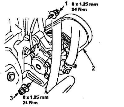
1 - fastening bolt;
2 - power steering pump drive belt;
3 - fixing bolt.
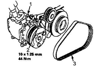
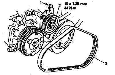
15. Remove the air conditioning compressor drive belt.
Engines V16A2, V16A4, V16A5, V16A6:
1. Loosen the tensioner pulley bracket bolt and the adjusting bolt, then remove the air conditioning compressor drive belt.
Engines V16A2, V16A4, V16A5, V16A6:
1 - adjusting bolt;
2 - tensioner pulley bracket bolt;
3 - air conditioning compressor drive belt.
In addition to engines V16A2, V16A4, V16A5, B16A6:
1. Loosen the tensioner pulley center nut and adjusting bolt, then remove the air conditioning compressor drive belt.
In addition to engines V16A2, V16A4, V16A5, V16A6:
1 - adjusting bolt;
2 - central nut of the tensioner roller;
3 - air conditioning compressor drive belt.
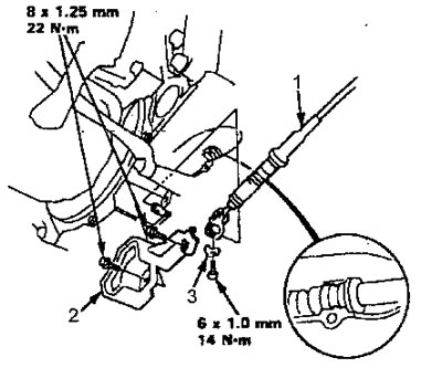
16. Remove the throttle cable, loosen the locknut, then remove the end of the cable from the sector.
Attention:
- Do not bend the cable when removing this. Always replace a damaged cable with a new one.
- Adjust the throttle cable during assembly.
Engines D14A3, D14A4, D15Z4, D15Z5, D16Y7:
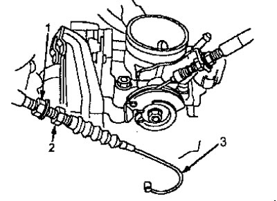
1 - lock nut;
2 - throttle valve drive cable;
3 - adjusting nut.
In addition to engines D14A3, D14A4, D15Z4, D15Z5, D16Y7:
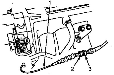
1 - throttle valve drive cable;
2 - lock nut;
3 - adjusting nut.
17. Remove the clutch slave cylinder assembly with tube and hose (mechanical checkpoint).
Attention:
- Do not disconnect the handset.
- Do not press the clutch pedal with the slave cylinder removed.
- Do not kink the tube.
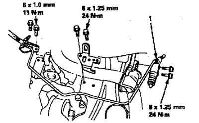
1 - working cylinder
18. Remove the transmission ground wire and hose clamp.
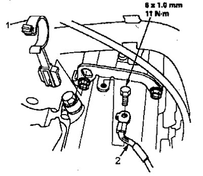
1 - clamp hose;
2 - gearbox ground wire.
19. Remove the control cable (CVT/HONDA MULTI MATIC).
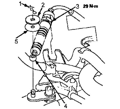
1 - cotter pin;
2 - washer;
3 - lock nut;
4 - plastic washer;
5 - control cable.
20. Disconnect the steering wheel speed sensor connector and remove the wiring harness clamp.
1 - connector for the sensor for changing the force on the steering wheel depending on the speed.
21. Remove the radiator cap.
When removing the radiator cap, wait until the coolant temperature drops to avoid getting burned.
22. Raise the lift to its full height.
23. Remove the front wheels and crankcase protection.
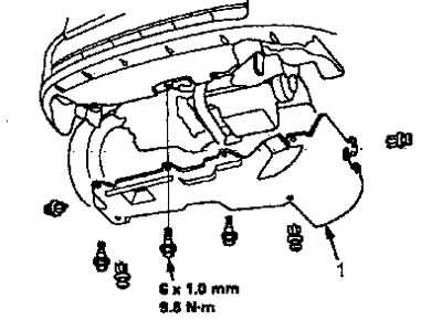
1 - protection crankcase _
24. Drain the coolant.
25. Drain the transmission oil or fluid. Reinstall the drain plug using a new washer.
26. Drink motor oil. Reinstall the drain bolt using a new washer.
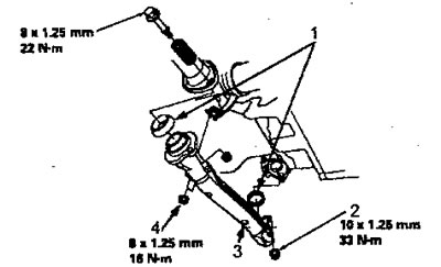
27. Remove the shift rod and longitudinal rod (mechanical checkpoint).
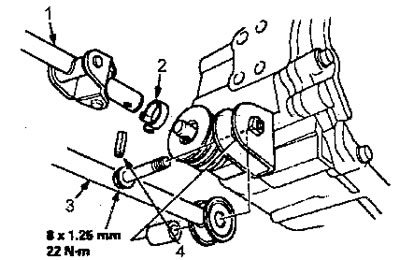
1 - gear shift rod;
2 - clamp;
3 - rod;
4 - spring pin 8 mm.
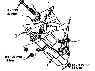
28. Remove the control cable (Models with automatic transmission).
Attention:
- Do not bend the cable. Always replace a damaged cable with a new one.
- Adjust the cable during assembly.
1 - control cable;
2 - control cable cover;
3 - lock washer.
29. Remove the air conditioning compressor.
Caution: Do not disconnect the air conditioning compressor hoses.

1 - Air conditioning compressor
30. (engines V16A2, V16A4, V16A5) Disconnect the heated oxygen sensor connector.
31. Remove exhaust pipe A.
Engines D15Z5, D15Z6, D16Y5 (models KE, KG), D16Y7:
1 - gaskets;
2 - self-locking nut;
3 - exhaust pipe A;
4 - self-locking nut.
Except engine D15Z5, D15Z6, D15Y5 (models KE, KG), D16Y7:
1 - connector for heated oxygen sensor;
2 - gaskets;
3 - gasket;
4 - self-locking nut;
5 - exhaust pipe A;
6 - self-locking nut.
32. Remove the right shock absorber fork.
33. Disconnect the lower control arm ball joints.
34. Remove the drive shafts.
35. Lower the lift.
36. Remove the upper and lower radiator hoses, as well as the heater hose.
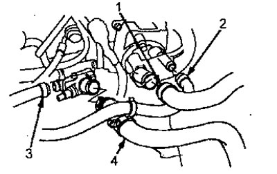
1 - upper radiator hose;
2 - heater hose;
3 - heater hose;
4 - lower radiator hose.
37. Remove the automatic transmission fluid cooler hoses, then plug the hoses and tube with plugs (models with automatic transmission, CVT/HONDA MULTI MATIC).
1 - automatic transmission fluid cooler hoses
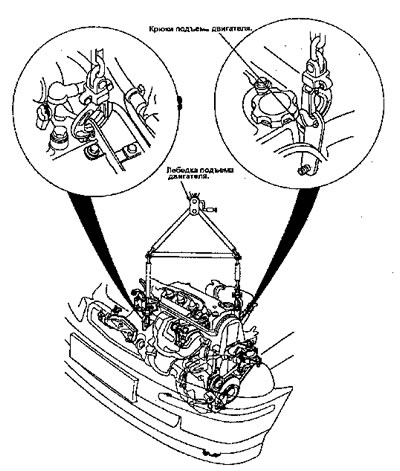
38. Connect the winch mount to the engine lift hooks.
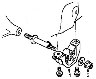
39. Remove the left and right front mounting mounts.
1 - left front support;
2 - nut.
1 - right front support;
2 - bolt.
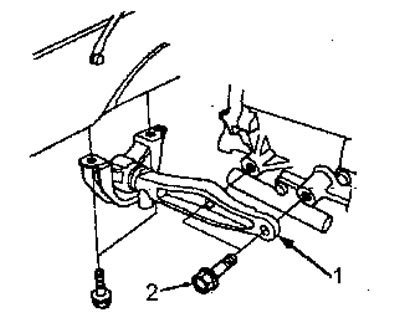
40. Remove the rear support.
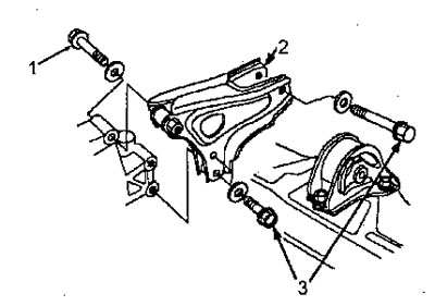
1 - bolt;
2 - rear support;
3 - bolts.
41. Remove the top bracket.
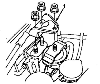
1 - top bracket _
42. Remove the transmission mounting bracket, then remove the transmission mount.
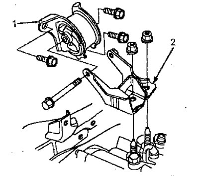
1 - gearbox support;
2 - gearbox mounting bracket.
43. Make sure that before removing the engine you have disconnected all hoses and connectors that may interfere with removal.
44. Slowly raise the engine approximately 150 mm. Double check that all hoses and wires are disconnected from the engine/transmission.
45. Raise the engine completely and remove it from the vehicle.