
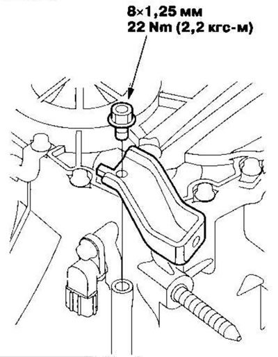
2. Install the front support.
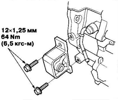
3. Install the rear support/bracket.
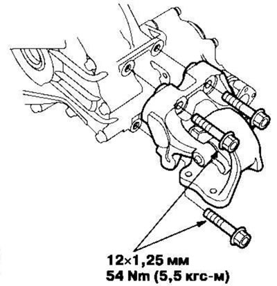
Note: 4WD model shown. 2WD model is similar.
4. Install the torque converter assembly (A) onto the drive shaft (B), installing a new O-ring (C).
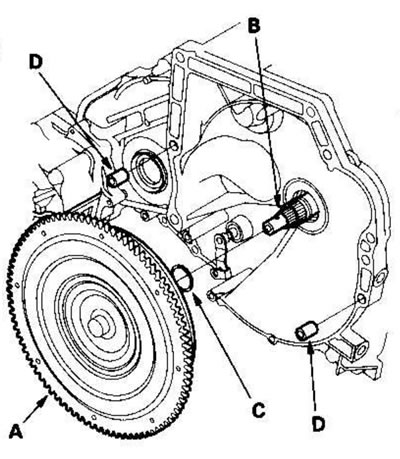
5. Insert the 14x20mm dowel pins (D) into the torque converter housing.
6. Support the gearbox with a jack and raise it to engine level.
7. Attach the gearbox to the engine, then tighten the mounting bolts on the gearbox housing.
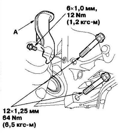
8. Install the stiffener (A).
9. Tighten the mounting bolts on the gearbox housing.
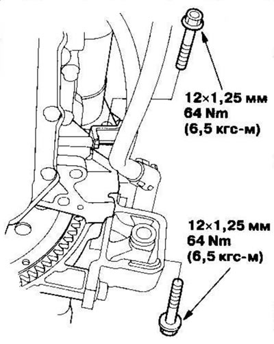
10. Tighten the mounting bolts on the gearbox housing.
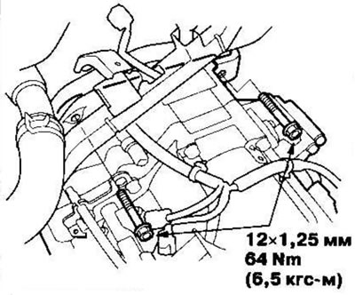
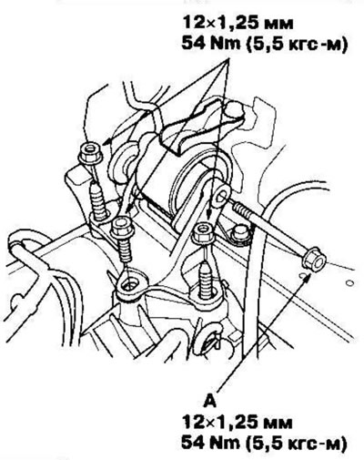
11. Install the gearbox support bracket. Install the support bolt (A) and tighten the bolt and nuts on the transmission support bracket to the specified torque, then tighten the support bolt to the specified torque.
12. Install new retaining rings (A) on the intermediate shaft (B).
13. Thoroughly clean the areas at the junction of the intermediate shaft and gearbox (differential) solvent or carburetor cleaner and dry with compressed air. Then insert the intermediate shaft into the differential. When installing the intermediate shaft, do not allow dust or other foreign particles to enter the gearbox.
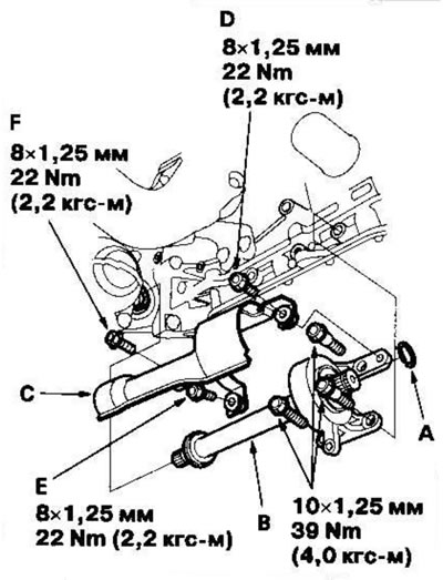
14. Install the intermediate shaft cover (C) by tightening the mounting bolts.
15. First tighten the right upper bolt (D) on the cover, then the right lower bolt (E), and finally the left bolt (F).
16. Install a new snap ring (A) onto the left drive shaft (B).
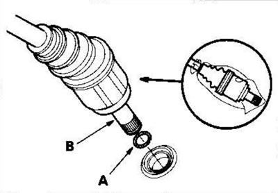
17. Insert the right and left drive shafts. When installing the left drive shaft into the differential, be careful not to allow dust or other foreign particles to enter the gearbox.
Note:
- Thoroughly clean the areas where the left drive shaft and gearbox meet (differential) solvent or carburetor cleaner and dry with compressed air.
- Fully turn the right and left steering knuckles and insert the left drive shaft into the differential until you feel its snap ring engage the axle gear. Slide the right-hand drive shaft onto the intermediate shaft splines until you feel the drive shaft engage the intermediate shaft retaining ring.
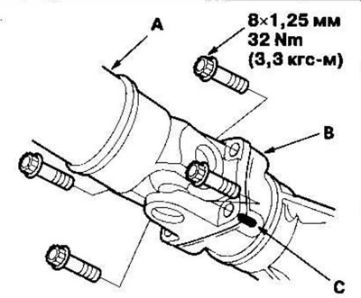
18. Attach the propeller shaft (A) to the transfer case connecting flange, aligning the marks (C).
19. Support the subframe (A) with a jack, placing a 10x10x100 cm wooden block (B) underneath it and lift it towards the body.
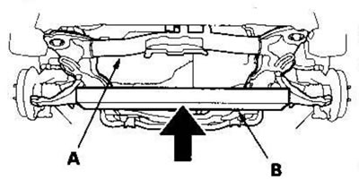
20. Install new mounting bolts into the subframe.
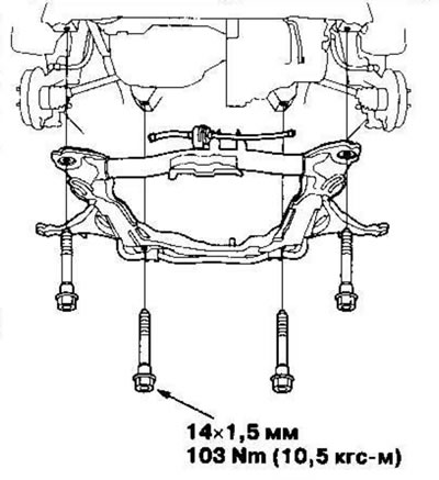
21. Apply marks (A) that correspond to the center of the subframe mounting bolts (B), then tighten the bolts to the required torque.
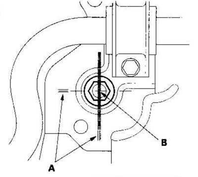
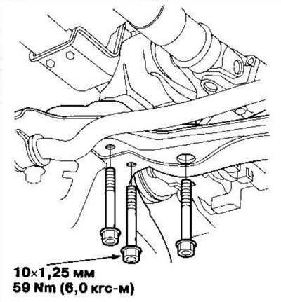
22. Screw the bolts into the rear support.
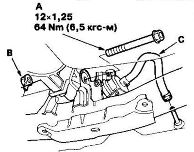
23. Install the bolt (A) and nut (B) into the front support, connect the ATF cooler hose (C) to the ATF cooler pipe, then secure the hose with the clamp.
24. Install the shift cable on 4WD models.
- Turn the point (A) on the shift cable (B) downward, then place the shift cable bracket (C) on the shift cable.
- Attach the shift cable end (D) to the control lever (E), then insert the check pin (F) into the hole in the control lever through the shift cable end.
- Secure the control pin with the spring clip (G). Do not kink the gear shift cable.
- Secure the shift cable bracket (H) with the bolts and install the cover (I) onto the shift cable by tightening the mounting bolts.
- First tighten the front bolt (J) on the cover, then the bottom bolt (K), and finally the center bolt (L).
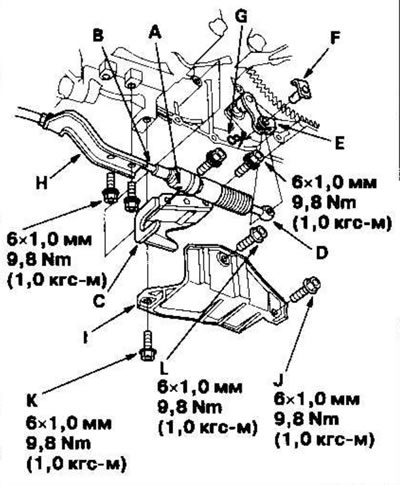
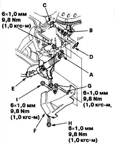
25. Install the shift cable on 2WD models.
- Attach the shift cable end (A) to the control lever (B), then insert the check pin (C) into the hole in the control lever through the shift cable end and secure the check pin with the spring clip (D). Do not kink the shift cable.
- Secure the shift cable bracket (E) with the bolts and install the cover (F) onto the shift cable by tightening the mounting bolts.
- First tighten the front bolt (G) on the cover, then the bottom bolt (H) and finally the center bolt (I).
26. Attach the torque converter (A) to the drive plate with eight bolts (A). Rotate the crankshaft pulley and tighten the bolts to the specified torque, then to the final torque in a crisscross pattern. After tightening the last bolt, check that the crankshaft rotates freely.
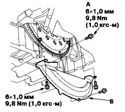
27. Install the cover (B) onto the torque converter.
28. Insert the ball joints (A) into the lower control arms (B), install the castle nuts (C) and install the spring clips (D). Install the spring clips from the inside of the vehicle with the hook side facing the front (E) of the vehicle to the specified depth.
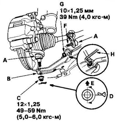
29. Insert the ball joints (F) into the lower control arms and install the nuts (G). Place a 5 mm socket wrench (H) on the tip of the ball joint pin and tighten the nuts.
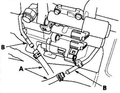
30. Connect the ATF cooler hoses (A) to the ATF cooler tubes (B).
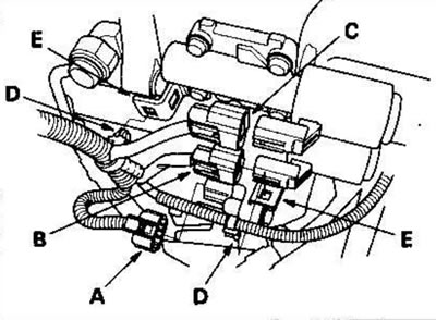
31. Connect the connector (A) to the gearshift solenoid valve harness, the connector to the clutch pressure control solenoid valve B and the connector to the solenoid valve C. Fasten the harness clamps (D) to the brackets (E).
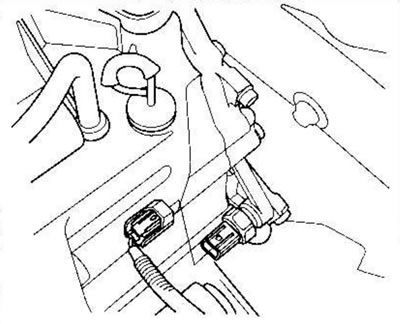
32. Connect the connector to the 3rd gear clutch pressure switch.
33. Install the mud deflector.
34. Unhook the winch chain from the suspension bracket (A) and remove the suspension bracket with the spacer sleeve (B) (if installed) from the engine.

35. Install the water pipe bolts (C) and tighten the bolt (D) into the air cleaner housing mounting bracket. Place the cap (E) on the harness.
36. Connect the connector (A) to the transmission range switch (A) and secure it to the bracket (B).
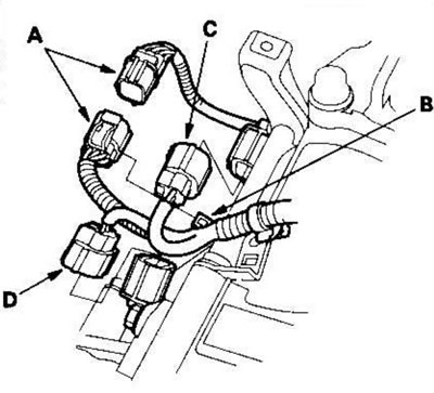
37. Connect the connectors to the speed sensor of the main (C) and intermediate (D) shafts.
38. Connect the connectors to the solenoid valve A for regulating the pressure in the automatic transmission clutches and to the pressure switch in the 2nd gear clutch (B), secure the harness clamps (C) to the brackets (D).
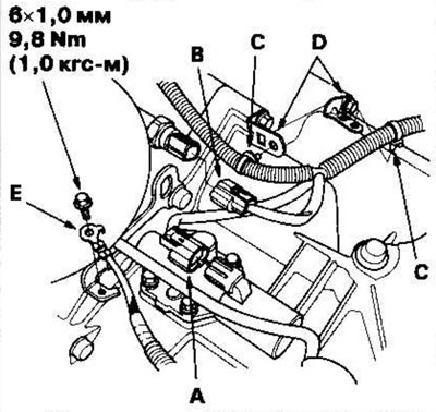
39. Connect the ground cable (E) to the gearbox.
40. Install the battery base, then secure the harness clamp to the bracket in the base.
41. Fill the gearbox with ATF transmission fluid.
42. Install the air cleaner housing and air intake pipe.
43. Install the battery tray and battery, then secure the battery with the hold-down bracket.
44. Connect the cable to the positive battery terminal, then to the negative one.
45. Apply the parking brake. Start the engine and shift the gearbox through all ranges three times.
46. Check the operation of the selector lever, the automatic transmission gear position indicator and the adjustment of the gear shift cable.
47. Check the front wheel alignment angles.
48. Start the engine, shift the transmission to position [P] or [N] and let it idle until it warms up to normal operating temperature (the radiator fan will turn on), then turn off the engine and check the ATF transmission fluid level.
49. Conduct a road test.
50. After road testing, loosen the front, rear and gearbox mount bolts.
Note: Tighten the support bolts in order.
51. Tighten the gearbox mount bolts.Tightening torque: 54 Nm (5.5 kgf·m)
52. Tighten the rear support bolts. Tightening torque: 64 Nm (6.5 kgf·m)
53. Tighten the front support bolts. Tightening torque: 54 Nm (5.5 kgf·m)