
The intake system consists of an air filter, an intake pipe, a throttle body, an idle control system, a cold start control mechanism, and an intake manifold. The throttle body with multi-point injection is two-chamber. The lower part of the housing is heated by liquid from the engine cooling system. The throttle body for two-point injection is single-chamber.
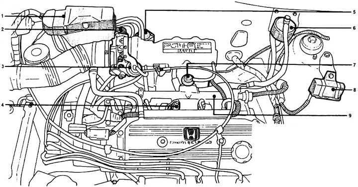
Pic. 11.1 Components of the emission control system and fuel system: 1 - control unit; 2 - throttle position sensor; 3 - throttle body; 4 - nozzle; 5- valve for supplying additional air; 6 - fuel filter; 7 - fuel pressure regulator; 8 - nozzle resistance; 9 - intake air temperature sensor.
The composition of the mixture when the engine is idling is regulated by a system consisting of an electronic module and executive solenoid valves. When the engine idle speed decreases, for example, when some additional load is turned on, the valve opens an additional bypass air passage, thereby restoring the normal idle speed.
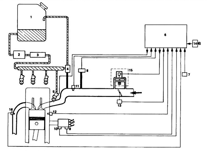
Pic. 11.2 Diagram of the PGM-FI system (multipoint): 1 - fuel tank; 2 - fuel pump; 3 - filter; 4 - fuel pressure regulator; 5 - nozzle valve; 6 - EMU; 7 - atmospheric pressure sensor; 8 - absolute pressure sensor; 9 - piston position sensor; 10 - TDC sensor; 11 - air temperature sensor; 12 - coolant temperature sensor; 13 - throttle position sensor; 14 - CO level adjustment potentiometer; 15 - additional air bypass (warm-up and idle adjustment); 16 - oxygen content sensor.
The same valve controls the processes of starting and warming up the engine at low temperatures.
When an automatic transmission is installed on a car during a cold start, additional loads occur that reduce the engine speed. To compensate for this phenomenon, a transmission idle compensation valve is used.
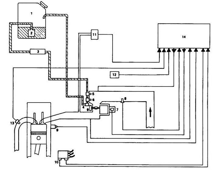
Pic. 11.3 Diagram of the PGM-FI system (point-to-point): 1 - fuel tank; 2 - fuel pump; 3 - filter; 4 - pressure regulator; 5 - main nozzle; 6 - additional nozzle; 7 - additional air control valve; 8 - air temperature sensor; 9 - coolant temperature sensor; 10 - shaft rotation angle sensor, TDC sensor; 11 - absolute pressure sensor; 12 - atmospheric pressure sensor; 13 - oxygen content sensor; 14 - EMU.
Electronic control module
The electronic module consists of an eight-bit processor and various sensors:
Crankshaft position sensor mounted in the distributor. The sensor has two rotors (TDC and "cylinder number") and sensors at their ends. Rotor "cylinder number" determines the position of the first cylinder as the basis for further injection control pulses, the rotor "TDC" controls ignition timing.
An absolute pressure sensor mounted on the intake manifold converts the pressure into electrical signals and feeds them to the processor. Together with sensors "TDC" And "cylinder" the duration of the injection is determined.
The atmospheric pressure sensor sets the compensation for fuel supply when atmospheric pressure changes.
The coolant temperature sensor compensates for fuel delivery based on engine temperature.
The air temperature sensor sets the fuel supply compensation when the ambient temperature changes.
The throttle position sensor is the main fuel control sensor.
The oxygen content sensor generates signals proportional to the oxygen content in the exhaust gases.
Start-up enrichment system (combination with starter).
Fuel supply system
The fuel supply system consists of a fuel pump, pressure regulator, injectors (four for multi-point and two for two-point injection schemes), additional resistance of the injectors and the main relay.
Fuel passes through the intake filter to the pump, through the check valve enters the main filter and from it to the nozzles. Excessive pressure build-up in the system is prevented by a non-return valve.
The fuel pressure regulator maintains a constant pressure differential between fuel and air in the intake manifold. This difference is 2.5 bar.
The nozzles are controlled by an electrovalve. When voltage is applied to the solenoid, the needle valve moves away from the seat and fuel enters the atomizer. The amount of fuel supplied to the engine is determined by the valve opening time or, which is also the duration of the voltage supply to the solenoid. The accuracy of fuel dosing depends on the state of the electrical parameters of the fuel supply system.