
Removal and installation
1. Remove the powertrain control unit.
2. Disconnect the connector (A) from the air flow direction change drive motor (B). Loosen the screws and remove the drive.
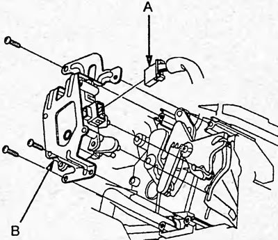
3. Install in the reverse order of removal.
4. Make sure the drive operates smoothly.
Examination
1. Disconnect the connector from the air flow direction change actuator.
2. Connect the battery to terminals "1" (+) and "2" (-), make sure the flap moves to the "VENT" position. Change the polarity and make sure the flap moves to the "DEFROST" position.
Caution: When stopping the electric motor, immediately disconnect the battery from the connector terminals.
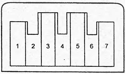
If the air flow direction change actuator does not work, replace it.
If the actuator operates unevenly, make sure the damper and rod move evenly.
If the flap and rod move evenly, replace the air flow direction change actuator. If the flap and rod move unevenly, repair them.
3. Using a digital multimeter (output current 1 mA or less with resistance 20 kOhm) make sure there is conductivity between terminal "7" and the terminals "3", "4", "5" and "6" during electric motor operation.
Air conditioning system diagnostics (manual air conditioner).
| Code | Component being diagnosed | Possible cause of the malfunction |
| 7 | Air flow mixing drive | Broken wiring |
| 8 | Air flow mixing drive | Short circuit in wiring |
| 9 | Air flow mixing drive | Electric motor jamming |
| 10 | Air flow direction change drive | Open or short circuit in wiring |
| 11 | Air flow direction change drive | Electric motor jamming |
| 12 | Heater fan | - Fuse - Wiring break or short circuit - Electric motor jammed |
| 13 | Air conditioning and heating control unit | Internal error |
| 14 | Evaporator Air Temperature Sensor | - Broken wiring - Malfunction of the air temperature sensor behind the evaporator |
| 15 | Evaporator Air Temperature Sensor | - Short circuit in wiring - Malfunction of the air temperature sensor behind the evaporator |