
Information about diagnostic tools
Checking the correct functioning of the components of the injection systems and reducing the toxicity of exhaust gases is carried out using a universal digital meter (multimeter). The use of a digital meter is preferred for several reasons. Firstly, it is quite difficult for analog devices to (sometimes impossible), determine the result of the indication with an accuracy of hundredths and thousandths, while when examining circuits that include electronic components, such accuracy becomes especially important. The second, no less important, reason is the fact that the internal circuit of a digital multimeter has a fairly high impedance (the internal resistance of the device is 10 million ohms). Since the voltmeter is connected in parallel to the circuit under test, the measurement accuracy is the higher, the less parasitic current will pass through the device itself. This problem is not significant when measuring relatively high voltages (9÷12 V), however, it becomes vital when diagnosing elements that produce low voltage signals, such as, for example, an oxygen sensor, where it is a matter of measuring fractions of a volt.
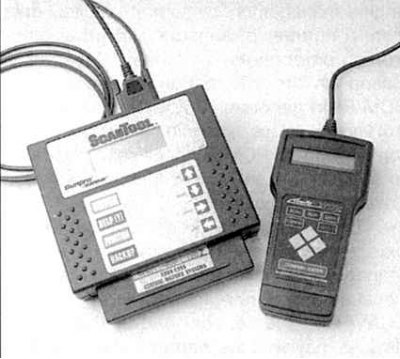
The most convenient device for diagnosing engine control systems of modern car models are manual scanner-type readers (see illustration below). First generation scanners are used to read fault codes for OBD-I systems. Before use, the reader should be checked for compliance with the model and year of manufacture of the vehicle being checked. Some scanners are multifunctional, due to the possibility of changing the cartridge depending on the model of the car being diagnosed (Ford, GM, Chrysler, etc.), others are tied to the requirements of regional authorities and are intended for use in certain areas of the world (Europe, Asia, USA, etc.).

With the introduction of a new generation of on-board diagnostics that meets the latest environmental legislation (OBD-II) Readers of a special design began to be produced. Some manufacturers have launched scanners designed for use by amateur mechanics at home - ask at car accessories stores.
General description of the OBD system
Models 1994 and 1995 issue equipped with the first generation on-board diagnostics system. Starting in 1996, Honda Motors launched models equipped with second-generation self-diagnosis systems that meet CARB and EPA standards and are called OBD-II. The system includes several diagnostic devices that monitor individual parameters of toxicity reduction systems and fix detected failures in the processor memory in the form of individual fault codes. The system also checks sensors and actuators, controls the vehicle's operating cycles, provides the possibility of freezing parameters and clearing the memory block.
The OBD-II processor memory data is read using a special scanner connected to the 16-pin diagnostic connector for reading the database (DLC), located under the instrument panel on the driver's side of the vehicle. All models of cars of the brands in question, starting from 1996, issue. equipped with the second generation OBD-II self-diagnosis system. The main element of the system is an onboard processor called the electronic control module (ECM), or power control module (RSM).
The ECM/PCM is the brain of the engine management system. The initial data is fed to the module from various information sensors and other electronic components (switches, relays, etc.). Based on the analysis of the data coming from the information sensors and in accordance with the basic parameters stored in the processor memory, the ECM / PCM generates commands for the operation of various control relays and actuators, thereby adjusting the engine's operating parameters and ensuring maximum engine efficiency with minimal fuel consumption.
Engine management/emission control system components are subject to a special extended warranty. Do not attempt to diagnose ECM/PCM failures or replace system components yourself before the warranty period expires - contact a Honda authorized service center.
Information sensors
Heated oxygen sensors (HO2S) – The sensor generates a signal whose amplitude depends on the oxygen content in the exhaust gases of the engine and the outside air.
crankshaft position sensor (TFR) - The sensor is used in first generation self-diagnosis systems (OBD-I) and informs the ECM/PCM of crankshaft position and engine speed.
TDC/crankshaft position/piston position sensor (TDC/TFR/CYP) – This sensor is used in second generation OBD-II systems. Based on the analysis of the information coming from the sensor, the ECM / PCM determines the position of the piston of the first cylinder, determines the moments of fuel injection and ignition.
Crankshaft fluctuation sensor (CKF) – The sensor monitors changes in the crankshaft speed. If the change in engine RPM is outside the allowable range, the ECM/PCM will issue a corresponding signal, which is regarded by the module as evidence of a misfire.
Engine coolant temperature sensor (EATING) – Based on the information coming from the sensor, the ECM/PCM makes the necessary adjustments to the composition of the air-fuel mixture and the ignition timing, and also monitors the operation of the EGR system.
intake air temperature sensor (IAT) – The ECM/PCM uses information from the IAT sensor to make adjustments to fuel flow, ignition timing settings, and to control EGR system operation.
Throttle position sensor (TPS) – The sensor is located on the throttle body and is connected to the throttle valve shaft. From the amplitude of the TPS signal output, the ECM/PCM determines the throttle opening angle (controlled by the driver from the gas pedal) and adjusts the fuel supply to the inlet ports of the combustion chambers accordingly. The failure of the sensor, or the weakening of its fastening, leads to interruptions in injection and violations of the stability of the idle speed.
Absolute pressure sensor in the pipeline (IDA) - The sensor monitors changes in pressure in the intake manifold associated with changes in engine speed and load, converting the information received into an amplitude signal. The ECM/PCM uses the information provided by the sensor when making adjustments to fuel delivery and ignition timing settings. The range of change of the output signal of the sensor is from 1.0 ÷ 1.5 V with the throttle closed (deep rarefaction), up to 4.0÷4.5 V with fully open damper (low vacuum). The sensor is also located on the throttle body.
Vehicle speed sensor (VSS) – As its name implies, the sensor informs the ECM/PCM of the current vehicle speed.
Fuel tank pressure sensor - The sensor is an integral component of the fuel vapor recovery system (EVAP) and serves to monitor the vapor pressure of gasoline in the tank. Based on information from the sensor, the ECM/PCM issues commands to operate the system purge solenoid valves.
Power steering pressure switch (PSP) – Based on the information from the sensor-switch, the ECM / PCM provides an increase in idle speed by triggering the IAC sensor in order to compensate for the increased loads on the engine associated with the operation of the power steering.
Knock sensor - The sensor reacts to changes in the level of vibrations associated with detonations in the engine. Based on the information coming from the sensor, the ECM/PCM makes the appropriate adjustments to the ignition timing.
Transmission sensors – In addition to the VSS data, the ECM/PCM also receives information from sensors placed inside the transmission or connected to it. These sensors include: turbine shaft speed sensor, ATF temperature sensor and gear selection sensor.
Air Conditioner Clutch Control Switch – When battery power is applied to the A/C compressor solenoid valve, the appropriate information signal is sent to the ECM/PCM, which regards it as evidence of an increase in engine load and adjusts its idling speed accordingly.
Executive devices
Main relay PGM-FI (fuel pump relay) – The ECM/PCM activates the fuel pump relay when the ignition key is turned to the START or RUN position. When the ignition is turned on, the activation of the relay provides a pressure rise in the power system. The relay is located in the power distribution box in the engine compartment of the vehicle. The description of procedures of check and replacement of the fuel pump is resulted in the Chapter Power and exhaust systems.
Fuel Injectors – The ECM/PCM ensures that each of the injectors is switched on individually according to the firing order. In addition, the module controls the duration of the opening of the injectors, determined by the width of the control pulse. The duration of the opening of the injector determines the amount of fuel injected into the cylinder. More detailed information on the principle of operation of the injection system, replacement and maintenance of injectors is given in Chapter Power and exhaust systems.
Ignition control module (ICM) – The module controls the functioning of the ignition coils by determining the required basic advance based on the commands issued by the ECM/PCM. On all models of cars considered in this Manual, the ICM built into the ignition distributor is used, for more details see Chapter Engine electrical equipment.
Idle speed control valve (IAC) – The IAC valve controls the amount of air bypassing the throttle when the throttle is closed or in the idle position. The ECM/PCM controls the opening of the valve and the resulting air flow. For more information on the IAC valve, see Chapter 4.
Canister purge valve – The charcoal canister purge solenoid valve is part of the EVAP system (EVAP) and, triggered by the ECM / PCM command, it blows the fuel vapors accumulated in the adsorber into the intake pipeline in order to burn them during the normal operation of the engine.
Reading trouble codes
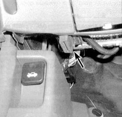
1. The control service connector is located under the instrument panel on the passenger side of the car (see accompanying illustration).
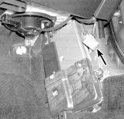
2. To read fault codes, it is necessary to close the connector terminals with a jumper wire and monitor the readings of the control lamp mounted in the dashboard of the car "Check engine" (valid for all models). The dedicated diagnostic reader can only be connected to the 16-pin database diagnostic connector (DLC), located on the left under the dashboard of the car (see accompanying illustration).
3. To view the fault codes recorded in the ECM / PCM memory, install a jumper in the control service connector (see illustration for paragraph 1), then turn on the ignition by turning the key to the ON position. If the codes of the faults that have occurred are entered in the processor memory, they will start to be sequentially displayed by the control lamp "Check engine" on the car's dashboard. The first digit of the two-digit code is displayed with long flashes of the lamp, the second - with short ones (for example, one long flash followed by six short flashes corresponds to code 16).
Note. If more than one code is stored in the memory of the control module, they will be displayed one by one, then, after a pause, the codes will be displayed again.
List of OBD-I Self-Diagnostic System Fault Codes
| Code number | Circuit or system | Actions to eliminate the cause of failure |
1 | Faulty ECM/PCM | Check the ECM/PCM electrical connector, if no signs of broken contacts can be found, drive the car to a service station for detailed diagnostics |
3 and 5 | Oxygen content | Check the oxygen sensor, its heater and wiring circuit (see Checking the condition and replacing the throttle position sensor (TPS)) |
4 | IDA | Check the MAP sensor and its electrical circuit (see Checking the condition and replacing the throttle position sensor (TPS)) |
6 | TFR | Check the CKP sensor and its electrical circuit (see Checking the condition and replacing the throttle position sensor (TPS)) |
7 | TPS | Check the TPS sensor and its electrical circuit (see Checking the condition and replacing the throttle position sensor (TPS)) |
8 | TDC (TDC) | Check the TDC sensor and its electrical circuit (see Checking the condition and replacing the throttle position sensor (TPS)) |
9 | CYP cylinder #1 | Check the CYP sensor and its electrical circuit (see Checking the condition and replacing the throttle position sensor (TPS)) |
10 | IAT | Check the IAT sensor and its electrical circuit (see Checking the condition and replacing the throttle position sensor (TPS)) |
12 | EGR | Check the condition of the system hoses, the EGR valve opening sensor and the EGR valve (see Checking the condition and replacing the intake air temperature sensor (IAT)) |
13 | barometric pressure | Drive the car to a service station for inspection |
14 | IAC valve | Check IAC valve and idle speed stabilization system (see chapter Power and exhaust systems) |
15 | Ignition output | Check the ignition system (see chapter Engine electrical equipment) |
16 | injection injector | Check the power system and fuel injection injectors (see chapter Power and exhaust systems) |
17 | VSS | Drive the car to a service station for inspection |
19 | Shut-off valve | On models with AT, check the condition of the e / m valve (see 4-speed and continuously variable automatic transmissions (at and cvt)) |
20 | ELD | Check the ELD system (see Checking the condition and replacing the TDC sensor / crankshaft position / piston position in the engine cylinders (TDC/TFR/CYP)) |
21 | Adjusting the phases of the timing and e / m valve lift | Checks e/m valves VTEC, Chapter Engine repair without removal from the car - Civic models |
22 | Timing timing adjustment and pressure sensor | See VTEC Pressure Sensor Tests, Chapter Engine repair without removal from the car - Civic models |
30 | Signal A A/T FI (models with AT) | Drive the car to a service station for inspection |
41 | Oxygen sensor heater | Check heater voltage signal (see chapter Power and exhaust systems) |
43 | Fuel supply system | Check fuel pressure and regulator condition (see chapter Power and exhaust systems), also check the oxygen sensors for signs of loss of vacuum |
48 | Heated l-probe | Check heater voltage signal (see chapter Power and exhaust systems) |
List of OBD-II Self-Diagnostic System Fault Codes
| Code number (number of MIL flashes) | Possible reason for rejection |
P0106 (5) | MAP sensor/engine efficiency problems |
P0107 (3) | MAP sensor input low |
P0108 (3) | MAP sensor input high |
Р0111 (10) | IAT sensor/engine efficiency problems |
Р0112 (10) | Low IAT sensor input |
Р0113 (10) | IAT sensor input high |
P0116 (86) | ECT sensor/engine efficiency problems |
P0117 (6) | Low ECT Sensor Input |
P0118 (6) | ECT Sensor High Input |
P0122 (7) | Low TPS sensor input |
P0123 (7) | TPS sensor input high |
P0131 (1) | Low voltage of the primary heated l-probe circuit (oxygen sensor 1) |
P0132 (1) | High voltage of the primary heated l-probe circuit (oxygen sensor 1) |
P0133 (61) | Slow response of the primary heated l-probe (oxygen sensor 1) |
P0135 (41) | Malfunction in a chain of a heater of a primary l-probe (oxygen sensor 1) |
P0137 (63) | Low voltage of the secondary heated l-probe circuit (oxygen sensor 2) |
P0138 (63) | High voltage of the secondary heated l-probe circuit (oxygen sensor 2) |
P0139 (63) | Slow response of the secondary heated l-probe (oxygen sensor 2) |
P0141 (65) | Malfunction in a chain of a heater of a secondary l-probe (oxygen sensor 2) |
P0171 (45) | Relean mixture |
P0172 (45) | Re-enrichment of the mixture |
P0300 | Random misfires |
P0301 (71) | Cylinder #1 Misfire |
P0302 (72) | Cylinder #2 Misfire |
P0303 (73) | Cylinder #3 Misfire |
Р0304 (74) | Cylinder #4 Misfire |
P0325 (23) | Malfunction in a chain of the gauge of a detonation |
P0335 (4) | Malfunction in the CKP sensor circuit |
P0336 (4) | CKP sensor/engine efficiency problems |
P0401 (80) | Too little EGR flow detected |
Р0420 (67) | Insufficient efficiency of the catalytic converter |
Р0441 (92) | EVAP purge not effective enough |
Р0452 (91) | Low fuel tank pressure sensor input (EVAP system) |
P0453 (91) | Fuel Tank Pressure Sensor High Input (EVAP system) |
P0500 (17) | Fault in the VSS circuit |
P0501 (17) | VSS Sensor / Engine Efficiency Problems |
P0505 (14) | Malfunction in the IAC sensor circuit |
P0700 (70) | AT |
P0715 (70) | AT |
P0720 (70) | AT |
P0725 (70) | AT |
P0730 (70) | AT |
P0740 (70) | AT |
P0753 (70) | AT |
P0758 (70) | AT |
R1106 (13) | BARO sensor/engine efficiency problems |
R1107 (13) | BARO Sensor Input Low |
R1108 (13) | BARO sensor input high |
R1121 (7) | Throttle opening greater than expected |
R1122 (7) | Throttle opening greater than expected |
R1128 (5) | The absolute pressure in the pipeline is lower than expected |
R1129 (5) | The absolute pressure in the pipeline is higher than expected |
R1162 (48) | Malfunction in a chain of primary l-probe (oxygen sensor 1) |
R1163 (61) | Too slow response of the primary l-probe (oxygen sensor 1) |
R1164 (61) | Primary l-probe/engine efficiency problems |
R1165 (61) | Primary l-probe/engine efficiency problems |
R1166 (41) | Malfunction in a chain of primary l-probe (oxygen sensor 1) |
R1167 (41) | Malfunction in a chain of a heater of a primary l-probe (oxygen sensor 1) |
R1168 (48) | Low input signal LABEL of the primary l-probe (oxygen sensor 1) |
R1169 (48) | High input signal LABEL primary l-probe (oxygen sensor 1) |
R1259 (22) | VTEC system malfunction |
R1297 (20) | Low ELD input |
R1298 (20) | High ELD input |
R1300 (-) | Random failure |
R1301 (71) | Cylinder #1 Misfire |
R1302 (72) | Cylinder #2 Misfire |
R1303 (73) | Cylinder #3 Misfire |
R1304 (74) | Cylinder #4 Misfire |
R1336 (54) | CKF sensor instability |
R1337 (54) | No signal from CKF sensor |
R1359 (8) | CKP/TDC sensor disconnected |
R1361 (8) | Instability of CKP/TDC sensor readings |
R1362 (8) | No signal from TDC sensor |
R1381 (9) | CYP sensor instability |
R1381 (9) | No signal from CYP sensor |
R1456 (90) | There are fuel vapor leaks in the gas tank (EVAP) |
R1457 (90) | There are fuel vapor leaks in the carbon adsorber (EVAP) |
R1491 (12) | Insufficient degree of opening of the EGR valve |
R1498 (12) | The EGR valve opening sensor outputs too high a signal |
R1508 (14) | Malfunction in the IAC valve circuit (1) |
R1509 (14) | Malfunction in the IAC valve circuit (2) |
R1607 (-) | ECM/PCM internal circuit malfunction |
R1655 (30) | There is an open or short circuit in the TMA/TMV signal line |
R1705 (70) | AT malfunction |
R1706 (70) | AT malfunction |
R1753 (70) | AT malfunction |
R1758 (70) | AT malfunction |
R1768 (70) | AT malfunction |
R1785 (70) | AT malfunction |
R1790 (70) | AT malfunction |
R1791 (70) | AT malfunction |
R1793 (70) | AT malfunction |
P1870 (70) | AT malfunction |
R1873 (70) | AT malfunction |
R1879 (70) | AT malfunction |
R1885 (70) | AT malfunction |
R1886 (70) | AT malfunction |
R1888 (70) | AT malfunction |
R1890 (70) | AT malfunction |
R1891 (70) | AT malfunction |
Clearing ECM/PCM Memory
When a fault code is entered into the ECM / PCM memory, a warning lamp lights up on the vehicle's instrument panel "Check engine". The code remains stored in the module's memory until the power is removed from it. To clear the memory of the control module for 10÷15 seconds, remove the BACK-UP fuse from the mounting block located on the right side of the engine compartment (see chapter Onboard electrical equipment).
Note. Removing the fuse will also turn off the radio and erase its settings.