
It should be noted that the oxygen sensor is only capable of generating a signal voltage when warmed up to normal operating temperature (about 320°C). While the sensor is cold, the ECM/PCM operates in OPEN LOOP mode.
If, with the engine warmed up to normal operating temperature and / or running for at least two minutes, the oxygen sensor generates a stable signal with an amplitude of 0.45 V (at a speed of at least 1500 per minute), the self-diagnosis system stores the corresponding fault code in the ECM / PCM memory (see Checking the condition and replacing the TDC sensor / crankshaft position / piston position in the engine cylinders (TDC/TFR/CYP)). The code is also entered in the event of a malfunction in the sensor heater circuit.
In the event of a malfunction of the λ-probe or its circuit, the ECM / PCM goes into open loop mode, ignoring the information coming from the sensor and maintaining the air-fuel mixture at a certain predetermined level, providing sufficient engine efficiency.
The correct functioning of the oxygen sensor depends on the fulfillment of a combination of certain specific conditions:
- a) Electrical parameters: The stability of the low voltage amplitude signal generated by the sensor largely depends on the quality of the contact connections of the λ-probe circuit, which should be checked first of all in case of problems;
- b) Outside air supply: The design of the λ-probe provides for free circulation of outside air inside the sensor. When installing the probe, always check the patency of the air channels;
- c) Working temperature: The ECM/PCM does not respond to information from the λ-probe until the sensor has warmed up to normal operating temperature (about 320°C). this fact should not be overlooked when checking the correct functioning of the probe;
- d) Fuel quality: Correct functioning of the λ-probe becomes possible only if UNLEADED fuel is used for refueling the car!
In addition to the conditions listed in the previous paragraph, some special precautions must be observed when servicing the λ-probe:
- a) The oxygen sensor is equipped with a piece of electrical wiring permanently mounted in it and equipped with a contact plug, attempts to disconnect which can lead to irreversible failure of the sensor;
- b) Try to keep the sensor louvers or its electrical connector free of dirt and grease;
- c) Do not use any solvents to clean the oxygen sensor;
- d) Handle the λ-probe with extreme care, do not drop it and try not to shake it off;
- e) The silicone protective cover must be worn on the sensor in a strictly defined way so as not to be melted and not to impair the proper functioning of the probe.
Examination
1. Locate the sensor's electrical connector. From the reverse side of the connector, insert an unfolded paper clip into the signal wire contact socket (white or white-red) (see accompanying illustration).
Note. Identification of the contact terminals of the connector can be made using wiring diagrams (see chapter Onboard electrical equipment). Connect the positive lead of the voltmeter to the paper clip, ground the negative lead.
Note. The colors of the λ-probe electrical wiring insulation are also shown in the wiring diagrams (see chapter Onboard electrical equipment).
2. Watch the Meter (mV) during engine warm-up.
3. At the initial stage, the cold sensor must generate a constant signal with an amplitude of 0.1 ÷ 0.2 V (open loop mode). After about two minutes, the engine will reach normal operating temperature and the sensor reading will begin to fluctuate between 0.1 and 0.9 V (closed loop mode). If the system does not transition to closed loop mode, or transitions with an unacceptably long delay (lazy sensor), replace the λ probe.
4. Check up also serviceability of functioning of a heater of the oxygen gauge. Disconnect the probe wiring connector and connect an ohmmeter between the heater terminals (see wiring diagrams in Chapter Onboard electrical equipment this guide). The nominal resistance is 10÷40 Ohm.
5. Check the power supply to the heater. Disconnect the electrical connector and measure the voltage at it from the side of the harness (refer again to the wiring diagrams). With the ignition on (do not start the engine) The voltmeter should record the voltage of the battery. If there is no power, check the condition of the wiring on the circuit between the main relay, the ECM/PCM, and the oxygen sensor.
6. If the above checks fail, replace the λ-probe.
Replacement
Note. Turning the λ-probe on a cold engine can be extremely difficult due to thermal compression of the metal of the exhaust manifold / exhaust pipe. To avoid the risk of damage to components, warm up the engine for a couple of minutes before proceeding with the removal of the sensor - try not to burn yourself on the heated surfaces during the procedure.
1. Disconnect the negative cable from the battery. Jack up the car and place it on jack stands.
Attention! If the stereo system installed in the car is equipped with a security code, before disconnecting the battery, make sure that you have the correct combination to activate the audio system!
2. Disconnect the oxygen sensor wiring connector.
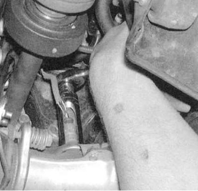
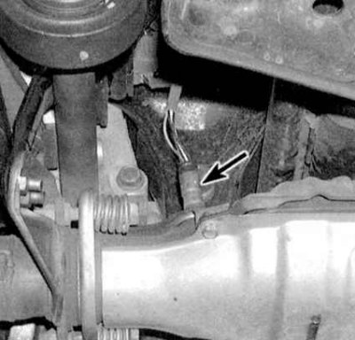
3. Carefully unscrew the probe from the exhaust manifold (see accompanying illustration).
4. Before screwing the sensor into place, lubricate its threaded part with anti-seize sealant (new sensors are usually already coated with the appropriate compound).
5. Screw the sensor into place and tighten it firmly.
6. Connect electrical wiring.
7. Lower the vehicle to the ground and test drive it. Check the control module memory for trouble codes.