
Examination
1. Follow the wiring harness from the TPS to the rear of the intake manifold and remove it from the bulkhead of the engine compartment to provide additional work space to check that the connectors are secure. Check the tightness of the connector on the sensor. Check the tightness of the fit in the terminal connector and the reliability of the wire connection to the contact terminals.
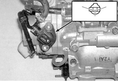
2a. Using a voltmeter, measure the reference voltage supplied from the ECM/PCM. Connect the positive probe of the meter to the yellow-blue wire terminal, ground the negative probe to ground. The voltmeter should register a reading of 5.0 V (see accompanying illustrations): TPS (Civic).
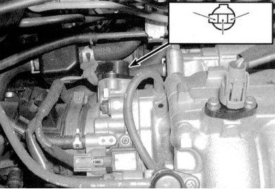
2b. TPS (Integra).
3. Now check the TPS signal voltage. With the engine off and throttle fully closed, connect the voltmeter leads to the red/black wire terminal and ground (see illustrations above). Gradually open the shutter, observing the readings of the voltmeter. With the throttle closed, the signal voltage should be 0.5 V and, gradually, increasing, reach a value of 4.5 V when the damper is fully opened, otherwise replace the TPS.
Note. To connect the voltmeter to the back side of the connector terminals, it is convenient to use an unbent metal paper clip.
4. When a malfunction is detected in the TPS circuit, the self-diagnosis system writes the corresponding trouble code to the ECM / PCM memory (see On-Board Diagnostic System (OBD) - the principle of operation and fault codes). In this case, the control module puts the system into emergency mode. Instead of the TPS signal, this uses an average value to maintain adequate engine output efficiency.
Replacement
The TPS is built into the throttle bodies and is only replaceable as part of the entire assembly (see chapter Power and exhaust systems).