
Contents: Removal ⇊ Installation ⇊
Removal
1. Loosen the nuts of the corresponding wheel. Jack up the front of the car and place it on supports. Remove the wheel.
2. Unbolt the flexible brake hose from the shock absorber assembly.
3. Disconnect the stabilizer bar from the lower suspension arm (see Removal and installation the front anti-roll bar with support bushings).
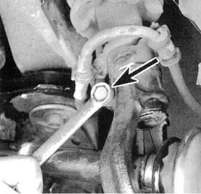
4. Place a jack under the lower control arm, providing support for it with the shock absorber assembly removed. Remove the tie bolt (see accompanying illustration).
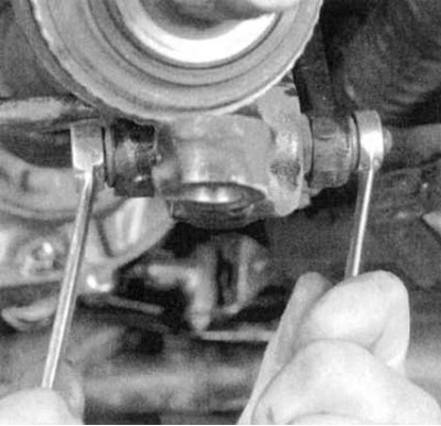
5a. Loosen the nut and remove the through bolt securing the fork to the lower suspension arm (see accompanying illustration).
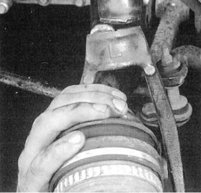
5b. Remove the fork. If necessary, tap the fork with a soft-faced hammer to separate it from the shock absorber.
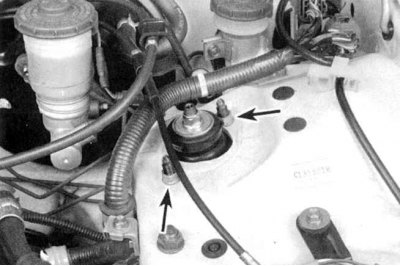
6. Having supported the shock absorber assembly, loosen the two nuts of its upper support (see accompanying illustration). Remove the assembly from under the vehicle through the wheel arch.
Installation
1. Insert the shock absorber assembly with the coil spring through the wheel arch into its regular place. Carefully insert the mounting studs into the holes of the upper support in the arch mudguard. Immediately screw the mounting nuts onto the studs, tightening them only by hand for now.
Note: Due to the significant weight of the shock absorber assembly, it is wise to enlist the help of an assistant.
2. Insert the lower end of the shock absorber into the damper fork. Make sure that the tabs on the back of the shock absorber body fit into the corresponding grooves in the fork.
3. Connect the damper fork to the lower suspension arm. Tighten the self-locking nuts to the specified torque, then tighten the fork pinch bolt to the specified torque.
4. Connect the anti-roll bar to the lower arm (see Removal and installation the front anti-roll bar with support bushings). Secure the flexible brake hose to its bracket on the shock absorber assembly. Tighten the bracket bolt securely.
5. Reinstall the wheel, then lower the vehicle to the ground and tighten the wheel nuts to the specified torque (see Specifications to the Chapter Routine maintenance).
6. Tighten the shock absorber assembly upper support nuts to the required torque.
The original can be found on the resource www.HondaBook.ru