
Contents: Removal/installation ⇊ Removal/installation ⇊
Removal/installation
1. Check the height of the diaphragm spring fingers using a digital indicator.
Standard (new): 0.8mm max.
Operational: 1.0 mm limit.
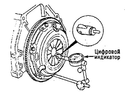
If the height exceeds the operating values, replace the clutch disc.
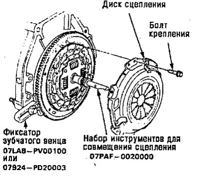
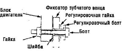
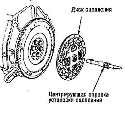
2. Install the special tool as shown.
3. To prevent deformation, unscrew the clutch disc mounting bolts in a crisscross pattern, then remove the clutch disc.
4. Inspect the clutch disc surface for wear, cracks and burning.
5. Inspect the diaphragm spring pins for wear in the release bearing contact area.
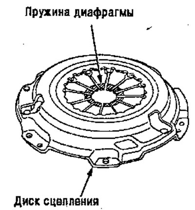
6. Check for deformation using a straightedge and feeler gauge.
Note: Check the clutch pressure plate at three points.
Standard (new): 0.03mm max.
Operational: 0.15 mm limit.
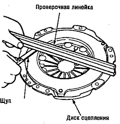
If the deformation exceeds the operating limits, replace the clutch disc.
Removal/installation
1. Remove the clutch disc and special tools.
2. Inspect the clutch disc linings for signs of slippage or oil. If the clutch disc is scorched or soaked with oil, replace it
3. Measure the thickness of the clutch disc.
Standard (new):
- Engines B16A2, B16A4, B16A6: 8.4-9.1 mm;
- Engine D16Y7: 8.5-9.1mm;
- Others: 8.3-9.0 mm.
- Operational limit: 5.5 mm.
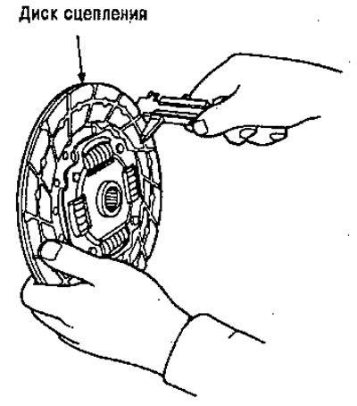
If the clutch disc thickness is less than the service values, replace the clutch disc.
4. Measure the depth from the surface of the overlay to the rivet on both sides.
Standard (new):
- D16Y7 Engine: 1.3-1.9mm;
- Other motors: 1.2-1.7 mm;
- Operation limit: 0.2 mm.
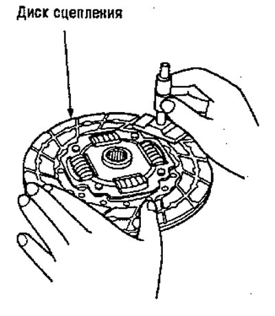
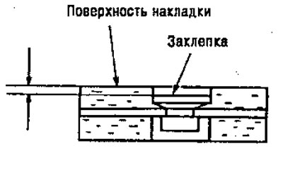
If the rivet depth is less than the service value, replace the clutch disc.